
Earth Is the Lords
5th Edition
ISBN: 9781121660069
Author: Caldwell, Taylor
Publisher: MCG/CREATE
expand_more
expand_more
format_list_bulleted
Concept explainers
Videos
Textbook Question
Chapter 2, Problem 2.2P
A single-phase power system is shown in Figure P2-1. The power source feeds a 100-kVA, 14/2.4-kV transformer through a feeder impedance of
The transformer’s equivalent series impedance referred to its low-voltage side is
The load on the transformer is 90 kW at 0.80 PF lagging and 2300 V.
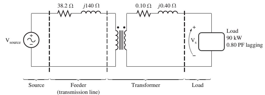
FIGURE P2-1
The circuit of Problem 2-2.
- What is the voltage at the power source of the system?
- What is the voltage regulation of the transformer?
- How efficient is the overall power system?
Expert Solution & Answer
Want to see the full answer?
Check out a sample textbook solution
Students have asked these similar questions
In the circuit in Figure 2, the capacitor and The circuit of resistance is defined as a load circuit.
A) Find the average power dissipated by the load circuit.
B) how much of the average power calculated in a) by the resistance in the load circuit and how much spent by the capacitor? Comment on the results obtained?
C) In the circuit in Figure 2, 2 / 3? A coil of is connected in series. In this case, Calculate the transformer ratio (n) to optimize power distribution to the load? Obtained comment on the result?
D) Calculate the complex power and reactive power dissipated by the load in the newly created circuit.
In the circuit in Figure 2, the capacitor connected to the a-b terminals of the transformer anda circuit consisting of resistance is defined as a load circuit.
a)Find the average power spent by the load circuit?
b) How much of the average power calculated in a) by the resistance in the load circuit and how muchspent by the capacitor? Comment on the results obtained?
In the circuit in Figure 2, the capacitor andThe circuit of resistance is defined as a load circuit.a) Find the average power dissipated by the load circuit?b) How much of the average power calculated in a) by the resistance in the load circuit and how muchspent by the capacitor? Interpreting the results obtained?c) In the circuit in Figure 2, with a resistance of 80 ohms 23?A coil of is connected in series. In this case,calculating transformer ratio () to optimize power delivery to the load? Obtainedinterpreting the result?d) Calculate the distributed load complex power and reactive power in the newly learned circuit?
Chapter 2 Solutions
Earth Is the Lords
Ch. 2 - Is the turns ratio of a transformer the same as...Ch. 2 - Why does the magnetization current impose an upper...Ch. 2 - What components compose the excitation current of...Ch. 2 - What is the leakage flux in a transformer? Why is...Ch. 2 - List and describe the types of losses that occur...Ch. 2 - Why does the power factor of a load affect the...Ch. 2 - Why does the short-circuit test essentially show...Ch. 2 - Why does the open-circuit test essentially show...Ch. 2 - How does the per-unit system of measurement...Ch. 2 - Why can autotransformers handle more power than...
Ch. 2 - What are transformer taps? Why are they used?Ch. 2 - What are the problems associated with the Y—Y...Ch. 2 - What is a TCUL transformer?Ch. 2 - How can three-phase transformation be accomplished...Ch. 2 - Prob. 2.15QCh. 2 - Can a 60-Hz transformer be operated on a 50-Hz...Ch. 2 - What happens to a transformer when it is first...Ch. 2 - What is a potential transform? How is it used?Ch. 2 - What is a current transformer? How is it used?Ch. 2 - A distribution transformer is rated at 18 kVA,...Ch. 2 - Why does one hear a hum when standing near a large...Ch. 2 - A 100-kVA, 8000/277-V distribution transformer has...Ch. 2 - A single-phase power system is shown in Figure...Ch. 2 - Consider a simple power system consisting of an...Ch. 2 - The secondary winding of a real transformer has a...Ch. 2 - When travelers from the USA and Canada visit...Ch. 2 - A 1000-VA, 230/115-V transformer has been tested...Ch. 2 - A 30-kVA, 8000/230-V distribution transformer has...Ch. 2 - A 150-MVA, 15/200-kV, single-phase power...Ch. 2 - A 5000-kVA, 230/13.8-kV, single-phase power...Ch. 2 - A three-phase transformer bank is to handle 500...Ch. 2 - A 100-MVA, 230/115-kV, Y three-phase power...Ch. 2 - Three 20-kVA, 24,000/277-V distribution...Ch. 2 - A 14,000/480-V, three-phase, Y-connected...Ch. 2 - A 13.8-kV, single-phase generator supplies power...Ch. 2 - An autotransformer is used to connect a 12.6-kV...Ch. 2 - Prove the following statement: If a transformer...Ch. 2 - A 10-kVA, 480/120-V conventional transformer is to...Ch. 2 - A 10-kVA, 480/120-V conventional transformer is to...Ch. 2 - Two phases of a 14.4-kV, three-phase distribution...Ch. 2 - A 50-kVA, 20,000/480-V, 60-Hz, single-phase...Ch. 2 - Prove that the three-phase system of voltages on...Ch. 2 - Prove that the three-phase system of voltages on...Ch. 2 - A single-phase, 10-kVA, 480/120-V transformer is...Ch. 2 - Figure P2-4 shows a one-line diagram of a power...
Knowledge Booster


Learn more about
Need a deep-dive on the concept behind this application? Look no further. Learn more about this topic, electrical-engineering and related others by exploring similar questions and additional content below.Similar questions
- Two transformers A and B give the following test results. With the low-tension side short-circuited, A takes a current of 10 A at 200 V, the power input being 1000 W. Similarly, B takes 30 A at 200 V; the power input being 1,500 W. On open circuit, both transformers give a secondary voltage of 2200 when 11,000 volts are applied to the primary terminals. These transformers are connected in parallel on both high tension and low-tension sides Calculate the current and power in each transformer when supplying a load of 200 A at 0.8 power factor lagging. The no-load currents may be neglected (Hint: Calculate ZA and ZB from S.C. test data) Answer [LA = 50.5 A, PA = 100 kW; IB = 151 A, PB = 252 kW] Please answer in typing format pleasearrow_forwardTwo transformers A and B give the following test results. With the low-tension side short-circuited, A takes a current of 10 A at 200 V, the power input being 1000 W. Similarly, B takes 30 A at 200 V the power input being 1,500 W. On open circuit, both transformers give a secondary voltage of 2200 when 11,000 volts are applied to the primary terminals. These transformers are connected in parallel on both high tension and low tension sides Calculate the current at transformer B when supplying a load of 200 A at 0.8 power factor lagging. Hint : Calculate ZA and ZB from S.C. test data) Answer in whole numberarrow_forwardInvestigate the different types of power transformers that exist today, mentioning their principle of operation (power transformer without mentioning their variants) Investigate the types of Instrument transformers (current and potential) and mention the principles of operation.arrow_forward
- On the plate of a single-phase transformer, it is written 20 kVa, 2000/200V, 50Hz. The results in the figure were obtained in the open-circuit test performed on the transformer. Draw the electrical equivalent circuit of the transformer for the high-voltage open-circuit no-load test by writing on the circuit element and on it. open circuit test high voltage side open circuit V= 200 A = 6a W = 200W closed circuit experiment low voltage side short circuit V= 200v A = 10 A W= 400Warrow_forwardIf all impedances in Figure Q2 are 15+j45 Ω. Calculate the neutral line current.arrow_forwardA transformer with a central tap was purchased that provides a voltage of 11Vac between the central tap and either of its ends. We want to make a regulated voltage source that is ± 12Vdc ... is it possible to make the source with the transformer you bought or need to go change it? What would you recommend?What are the minimum components that you must buy to make the voltage source? Just provide your view pleasearrow_forward
- A 2000-kVA, 6,600/400-V, 3-phase transformer is delta-connected on the high voltage side and star-connected on the low-voltage side. Determine its % resistance and % reactance drops, % efficiency and % regulation on full load 0.8 p.f. leading given the following data : S.C. test; H.V. data : 400 V, 175 A and 17 kW O.C. test; L.V. data: 400 V, 150 A and 15 kWarrow_forwardThe corrected instrument readings obtained from open and short-circuit test on 10- kVA, 450/120-v, 50-H transformer are O.C.test V1-120;l1 -4.2A ; w1-80 W; V1, w1 and I1 were read an the low voltage side 5.C.test v1-9.66 V; l1-22.2A ;W-120 W- with law voltage winding short-circuited Compute: i. Effiecincy and voltage regulation for an 80% lagging p.f. load Ii. Efficiency at half load and 80% laggig pfarrow_forwardTwo 6600/250-V transformers have the following short-circuit characteristics: Applied voltage 200 V, current 30 A, power input 1,200 W for one of the transformers; the corresponding data for the other transformer being 120 V, 20 A, and 1,500 W. All value are measured on the H.V. side with the L.V. terminals short-circuited. Find the approximate current and the power factor of each transformer when working in parallel with each other on the high and low voltage sides and taking a total load of 150 kW at a p.f. of 0.8 lagging from the high voltage bus bars.arrow_forward
- A 100 kVA transformer is connected to the supply line 24 hours a day In 6 hours, it delivers 90 kW at 0.9 pf. for 4 hours, it supplies 25 kW at 0.5 pf, and for the rest of the day it operates without a load. Its core loss at rated voltage is 1000 W and its copper loss with full load current is 1680 W What is the all-day efficiency of this transformer?arrow_forward1) Open and short circuit test tests are carried out in a 1100 VA single -phase transformer, 230/115 V, 60 Hz. Both tests are They carry out with instrumentation on the high voltage side and the Following data: Open circuit test VCA = 230 V ICA = 0,10 A PCA = 5.2 W Short circuit test Vcc = 10,8 V Icc = 4,35 A PCC = 11.75 W a) Find the equivalent circuit referred to the high voltage side. b) Find the transformer voltage regulation for conditions Nominal and F.P. 0.8 in advance.arrow_forwardA 15-KVA,2400/240-V transformer is to be tested to determine its excitation branch components,its series impedence and its voltage regulation.The following test data have been taken from the primary side of the transformer: *Open circuit test Voc=2400V loc=0.25 Poc=50W *short circuit test Vsc=48V Isc=6.0A Psc=200W The data have been taken by using the connection of open circuit test and short circuit test: a)Find the equivalent circuit of the transformer referred to the high voltage side. b)Find the equivalent circuit of transformer referred to the low voltage side. c)Calculate the full load voltage regulation at 0.8 lagging power factor and 0.8 leading power factor. What is the efficiency of the transformer at full load with a power factor of 0.8 lagging ?arrow_forward
arrow_back_ios
SEE MORE QUESTIONS
arrow_forward_ios
Recommended textbooks for you
 Introductory Circuit Analysis (13th Edition)Electrical EngineeringISBN:9780133923605Author:Robert L. BoylestadPublisher:PEARSON
 Delmar's Standard Textbook Of ElectricityElectrical EngineeringISBN:9781337900348Author:Stephen L. HermanPublisher:Cengage Learning
 Programmable Logic ControllersElectrical EngineeringISBN:9780073373843Author:Frank D. PetruzellaPublisher:McGraw-Hill Education
 Fundamentals of Electric CircuitsElectrical EngineeringISBN:9780078028229Author:Charles K Alexander, Matthew SadikuPublisher:McGraw-Hill Education
 Electric Circuits. (11th Edition)Electrical EngineeringISBN:9780134746968Author:James W. Nilsson, Susan RiedelPublisher:PEARSON
 Engineering ElectromagneticsElectrical EngineeringISBN:9780078028151Author:Hayt, William H. (william Hart), Jr, BUCK, John A.Publisher:Mcgraw-hill Education,
Introductory Circuit Analysis (13th Edition)
Electrical Engineering
ISBN:9780133923605
Author:Robert L. Boylestad
Publisher:PEARSON
Delmar's Standard Textbook Of Electricity
Electrical Engineering
ISBN:9781337900348
Author:Stephen L. Herman
Publisher:Cengage Learning
Programmable Logic Controllers
Electrical Engineering
ISBN:9780073373843
Author:Frank D. Petruzella
Publisher:McGraw-Hill Education
Fundamentals of Electric Circuits
Electrical Engineering
ISBN:9780078028229
Author:Charles K Alexander, Matthew Sadiku
Publisher:McGraw-Hill Education
Electric Circuits. (11th Edition)
Electrical Engineering
ISBN:9780134746968
Author:James W. Nilsson, Susan Riedel
Publisher:PEARSON
Engineering Electromagnetics
Electrical Engineering
ISBN:9780078028151
Author:Hayt, William H. (william Hart), Jr, BUCK, John A.
Publisher:Mcgraw-hill Education,
TRANSFORMERS - What They Are, How They Work, How Electricians Size Them; Author: Electrician U;https://www.youtube.com/watch?v=tXPy4OE7ApE;License: Standard Youtube License