
EBK ELECTRICAL ENGINEERING
7th Edition
ISBN: 8220106714201
Author: HAMBLEY
Publisher: YUZU
expand_more
expand_more
format_list_bulleted
Concept explainers
Videos
Textbook Question
Chapter 2, Problem 2.47P
The circuit of Figure P2.47 is similar to networks used en digital-to-analog converters. For this problem, assume that the circuit continues indefinitely to the night. Find the values of i1, i2, i3, and i4. How is in+2 related to in? What is the value of i18?(Hint: See Problem P2.12) 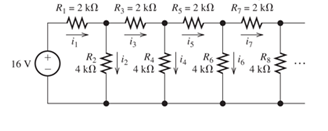
Figure P2.47
Expert Solution & Answer
Want to see the full answer?
Check out a sample textbook solution
Students have asked these similar questions
Explain five (5) applications of the hall effects
With the aid of a diagram, explain how a P-N Junction is form.
iii. State five (5) application of PN Junction, and explain the property of the PN junction that make
those application possible.
Explain what carrier mobility is and elaborate on the factors that influence carrier mobility.
A 80 V rms is stepped down to 18V rms by a transformer. The output from the transformer is
rectified using a half wave rectifier circuit and connected to a 47.5 Ω load resistor.
Draw a circuit diagram of this arrangement and the waveform at each stage.
Calculate the following about the circuit in Figure 2.1 (If silicon diodes are employed in the
rectification);
the peak value of the output voltage considering the drop across each diode,
the average voltage,
iii. The current through the load resistor,
The current diode,
The frequency of the output signal,
Calculate the efficiency of the full wave rectifier expressed in percentage.
vii. Sketch…
My circuit is a Wall-Wall rectifier circuit. The transformer is taking in 120Vac from the wall and stepping it down to 22Vac. A set of 4 diodew and a capacitor then supply 22 VDC with a ripple voltage of 50mV and a ripple frequency of 120Hz. Which diode should be purchased and why?
Q1: Draw the d.c load line for the circuit shown in figure.
NO SIGNAL
VBB
Vcc= 12.5 V
www
Re=2.5 k2
Chapter 2 Solutions
EBK ELECTRICAL ENGINEERING
Ch. 2 - Reduce each of the networks shown in Figure P2.1...Ch. 2 - A 4- resistance is in series with the parallel...Ch. 2 - Find the equivalent resistance looking into...Ch. 2 - Suppose that we need a resistance of 1.5 k and...Ch. 2 - Find the equivalent resistance between terminals a...Ch. 2 - Find the equivalent resistance between terminals a...Ch. 2 - What resistance in parallel with 120 results in...Ch. 2 - Determine the resistance between terminals a and b...Ch. 2 - Two resistances having values of R and 2R are in...Ch. 2 - A network connected between terminals a and b...
Ch. 2 - Two resistances R1 and R2 are connected in...Ch. 2 - Find the equivalent resistance for the infinite...Ch. 2 - If we connect n 1000- resistances in parallel,...Ch. 2 - The heating element of an electric cook top has...Ch. 2 - We are designing an electric space heater to...Ch. 2 - Sometimes, we can use symmetry considerations to...Ch. 2 - The equivalent resistance between terminals a and...Ch. 2 - Three conductances G1 G2, and G3 are in series....Ch. 2 - Most sources of electrical power behave as...Ch. 2 - The resistance for the network shown in Figure...Ch. 2 - Often, we encounter delta-connected loads such as...Ch. 2 - What are the steps in solving a circuit by network...Ch. 2 - Find the values of i1 and i2 in Figure P2.23....Ch. 2 - Find the voltages v1 and v2 for the circuit shown...Ch. 2 - Find the values of v and i in Figure P2.25. Figure...Ch. 2 - Consider the circuit shown in Figure P2.24....Ch. 2 - Find the voltage v and the currents i1 and 12 for...Ch. 2 - Find the values of vs, v1, and i2 in Figure P2.28....Ch. 2 - Find the values of i1 and i2 in Figure P2.29....Ch. 2 - Consider the cirrcuit shown in Figure P2.30 Find...Ch. 2 - Solve for the values of i1, i2, and the powers for...Ch. 2 - The 12-V source in Figure P2.32 is delivering 36...Ch. 2 - Refer to the circuit shown in Figure P2.33. With...Ch. 2 - Find the values of i1 and i2 in Figure P2.34. Find...Ch. 2 - Find the values of i1 and i2 in Figure P2.35...Ch. 2 - Use the voltage-division principle to calculate...Ch. 2 - Use the current-division principle to calculate i1...Ch. 2 - Use the voltage-division principle to calculate...Ch. 2 - Use the current-division principle to calculate...Ch. 2 - Suppose we need to design a voltage-divider...Ch. 2 - A source supplies 120 V to the series combination...Ch. 2 - We have a 60- resistance, a 20- resistance, and...Ch. 2 - A worker is standing on a wet concrete floor,...Ch. 2 - Suppose we have a load that absorbs power and...Ch. 2 - We have a load resistance of 50 that we wish to...Ch. 2 - We have a load resistance of 1 k that we wish to...Ch. 2 - The circuit of Figure P2.47 is similar to networks...Ch. 2 - Write equations and solve for the node voltages...Ch. 2 - Solve for the node voltages shown in Figure P2.49....Ch. 2 - Solve for the node voltages shown in Figure P2.50....Ch. 2 - Given R1=4 , R2=5 , R2=8 , R4=10 , R5=2 , and...Ch. 2 - Determine the value of i1 in Figure P2.52 using...Ch. 2 - Given R1=15 , R5=5 , R3=20 , R4=10 , R5=8 , R6=4 ,...Ch. 2 - In solving a network, what rule must you observe...Ch. 2 - Use the symbolic features of MATLAB to find an...Ch. 2 - Solve for the values of the node voltages shown in...Ch. 2 - Solve for the node voltages shown in Figure P2.57....Ch. 2 - Solve for the power delivered to the 8- ...Ch. 2 - Solve for the node voltages shown in Figure P2.59....Ch. 2 - Find the equivalent resistance looking into...Ch. 2 - Find the equivalent resistance looking into...Ch. 2 - Figure P2.62 shows an unusual voltage-divider...Ch. 2 - Solve for the node voltages in the circuit of...Ch. 2 - We have a cube with 1- resistances along each...Ch. 2 - Solve for the power delivered to the 15- resistor...Ch. 2 - Determine the value of v2 and the power delivered...Ch. 2 - Use mesh-current analysis to find the value of i1...Ch. 2 - Solve for the power delivered by the voltage...Ch. 2 - Use mesh-current analysis to find the value of v...Ch. 2 - Use mesh-current analysis to find the value of i3...Ch. 2 - Use mesh-current analysis to find the values of i1...Ch. 2 - Find the power delivered by the source and the...Ch. 2 - Use mesh-current analysis to find the values of i1...Ch. 2 - Use mesh-current analysis to find the values of i1...Ch. 2 - The circuit shown in Figure P2.75 is the dc...Ch. 2 - Use MATLAB and mesh-current analysis to determine...Ch. 2 - Connect a 1-V voltage source across terminals a...Ch. 2 - Connect a 1-V voltage source across the terminals...Ch. 2 - Use MATLAB to solve for the mesh currents in...Ch. 2 - Find the Thévenin and Norton equivalent circuits...Ch. 2 - We can model a certain battery as a voltage source...Ch. 2 - Find the Thévenin and Norton equivalent circuits...Ch. 2 - Find the Thévenin and Norton equivalent circuits...Ch. 2 - Find the Thévenin arid Norton equivalent circuits...Ch. 2 - An automotive battery has an open-circuit voltage...Ch. 2 - A certain two-terminal circuit has an open-circuit...Ch. 2 - If we measure the voltage at the terminals of a...Ch. 2 - Find the Thévenin and Norton equivalent circuits...Ch. 2 - Find the maximum power that can be delivered to a...Ch. 2 - Find the maximum power that can be delivered to a...Ch. 2 - Figure P2.91 shows a resistive load RL connected...Ch. 2 - Starling from the Norton equivalent circuit with a...Ch. 2 - A battery can be modeled by a voltage source Vt in...Ch. 2 - Use superposition to find the current i in Figure...Ch. 2 - Solve for is in Figure P2.49 by using...Ch. 2 - Solve the circuit shown in Figure P2.48 by using...Ch. 2 - Solve for i1 in Figure P2.34 by using...Ch. 2 - Another method of solving the circuit of Figure...Ch. 2 - Use the method of Problem P2.98 for the circuit of...Ch. 2 - Solve for the actual value of i6 for the circuit...Ch. 2 - Device A shown in Figure P2.101 has v=3i2 for i 0...Ch. 2 - The Wheatstone bridge shown in Figure 2.66 is...Ch. 2 - The Wheatstone bridge shown in Figure 2.66has...Ch. 2 - In theory, any values can be used for R1 and R3 in...Ch. 2 - Derive expressions for the Thévenin voltage and...Ch. 2 - Derive Equation 2.93 for the bridge circuit of...Ch. 2 - Prob. 2.107PCh. 2 - Explain what would happen if, in wiring the bridge...Ch. 2 - Match each entry in Table T2.1(a) with the best...Ch. 2 - Consider the circuit of Figure T2.2 with vs=96V ,...Ch. 2 - Write MATLAB code to solve for the node voltages...Ch. 2 - Write a set of equations that can be used to solve...Ch. 2 - Determine the Thévenin and Norton equivalent...Ch. 2 - According to the superposition principle, what...Ch. 2 - Determine the equivalent resistance between...Ch. 2 - Transform the 2-A current source and 6- ...
Knowledge Booster


Learn more about
Need a deep-dive on the concept behind this application? Look no further. Learn more about this topic, electrical-engineering and related others by exploring similar questions and additional content below.Similar questions
- Q2: A buck converter feeding a variable resistive load is shown in the figure. The switching frequency of the switch S is 100 kHz and the duty ratio is 0.6. The output voltage Vo is 36 V. Assume that all the components are ideal, and that the output voltage is ripple-free. The value of R (in Ohm) that will make the inductor current (i.) just continuous is 5 mH in 60 V + 36 V Vo R Answer : 2480 to 2520arrow_forwardd) A DC power supply at the input is used to generate a 10 V output voltage of the Zener regulator as shown in Figure Q2d. The maximum current rating of the Zener diode, Izm = 30 mA. Calculate the range of the output load, R_ that will maintain the Zener diode in the 'ON' state. R = 250R IR + Iz + Vz = 10 V Izm = 30 mA Vi = 20V RL VL Figure Q2darrow_forwardQ2 A circuit with an unstable DC voltage source Vs and output Vzis shown in Figure Q2. The unstable DC voltage source has nominal 20V but it can vary as much as +/- 20%. The circuit contains a zener diode. The zener diode has voltage Vz = 7.2V when Iz 2mA, rz = 202 and its IzK = 0.5mA. Using the zener diode mode and without making further approximation, answer the following questions. Rs = 2502 Vz %3D Vs RL Figure Q2. a) Detemine RL such that Vz = 8V when Vs at its nominal level. b) Based on the result in a), determine the difference between the maximum Vz and the minimum Vz.arrow_forward
- The voltage regulation can be equal to zero :when .The t and current is not too highO .The p.f. is leading p.f. for any possible current O .The p.f. is lagging p.f. for rated current Oarrow_forwardQUESTION 2 a) b) Figure Q2a shows a parallel clipper circuit. Analyze the circuit and hence sketch the output waveform for one complete cycle of the input. R own V₁ 10 Vi (V) A -20 15- -15 t(s) t(s) Figure Q2a Determine the output voltage, V, and hence sketch the output voltage waveform for the clamper circuit shown in Figure Q2b. C Figure Q2b Si Si 5 V 3V V₂ R Voarrow_forwardc) Using a Si diode, design a clamper circuit that will result in the desired output waveform as shown in Figure Q2c. Show overall analysis to justify the proposed design. Vi V. 20 Designed Clamper Circuit - 3 V -20 - 43 V - Figure Q2carrow_forward
- Draw circuit diagram of a full-wave controlled rectifier and draw the wave shapes of output voltage and current for R-L load with sinusoidal input. You have to design a full-wave AC to DC converter circuit to have output average voltage of 40 and 50 W power to a 100 Ω resistive load from a source of 60 V. Is the design feasible? Why?arrow_forwardConsider the following step up converter with a resistive load of value R=5 Q2. It is supplied by a DC power source of magnitude V₁-200 V. The switching frequency is 5 kHz and the duty cycle k is first set to 0.5 and the inductance used within the circuit has a value of L=10 mH. The switch is supposed to be ideal. Suppose the solutions for charging and discharging modes are given as below: Charging mode, Initial value Il Discharging mode, Initial value I2 O + V₂ o L ܀ + VL ▷ D₁ Chopper Load Vo 1₂ = i 4₁ = Vekz R 1 1- e-(1-k)z R i₁ Vekz e-(1-k)z + 1-e-(1-k)z R R Circuit Analysis: 1. Analyze briefly the principle of operation of this circuit. 2. Demonstrate that the ripple currents can be written as follow: Vs ΔΙ = .k.T L Ai 3. Demonstrate that the average output voltage can be written as follow: V₁ = V₁₁1=K² + with z = Numerical Application: 4. Find the average output voltage, the minimum and maximum load current values. 5. Find the peak to peak load current value. 6. Find the average…arrow_forwardRefer to the circuit on the right. VEB = 0.7 V, when the BE junction is conducting. VECsat = 0.2 V B Vref = 2.2 V (Use two decimal places.) = ∞ VREF IL +5 V R LOAD Figure 2 a. What should be the value of R in ohms if IL is to be maintained at 146 mA under changing load conditions? b. In order to maintain this load current, what should be the maximum allowable load resistance in ohms?arrow_forward
- Given the zener voltage at 9V and the zener power at 1W, what is the range of allowable values of Iz (operating values). a) 0.11A b) 22mA to 89mA c) 9A d) 0.11A to 9Aarrow_forwardThe Figure 2 shows an electronic circuit designed for supplying power to a load (R1). The supply voltage 235V (RMS, AC) at frequency of 50HZ. The required DC voltage and power for the load are 24V and 3.6 W respectively. The Electrical Components of this AC to DC converter are: A full-wave rectifier to convert AC voltage to DC voltage. A regulator with transistor and Zener diode to ensure a constant voltage and power for the load. D1 Iide 91 Vaut VLoad D2 D3 Vde VI sine R1 RL Regulate Reetifier Figure 2. Complete Circuit Assume that the diodes are real diodes (NOT ideal diodes). The following information is available: The collector to base resistor of the regulator R1 = 5.0 k The transistor Q1 with B value of 24 is used for the regulator circuit. Determine the following quantities for this electronic device and fill the table below: Question Answer The voltage of Zener Diode (Vz) The current in R1 The DC current into the regulator | (Idc) Base current of transistor (IB) Collector…arrow_forwardFor the circuit in the figurea) Determine the time constant.b) Write the mathematical expression for IL, VL and VR, after the switch is closed.c) Determine IL, VL for one, three and five time constants.d) Draw the waveforms of IL, VL and VR.arrow_forward
arrow_back_ios
SEE MORE QUESTIONS
arrow_forward_ios
Recommended textbooks for you
 Introductory Circuit Analysis (13th Edition)Electrical EngineeringISBN:9780133923605Author:Robert L. BoylestadPublisher:PEARSON
 Delmar's Standard Textbook Of ElectricityElectrical EngineeringISBN:9781337900348Author:Stephen L. HermanPublisher:Cengage Learning
 Programmable Logic ControllersElectrical EngineeringISBN:9780073373843Author:Frank D. PetruzellaPublisher:McGraw-Hill Education
 Fundamentals of Electric CircuitsElectrical EngineeringISBN:9780078028229Author:Charles K Alexander, Matthew SadikuPublisher:McGraw-Hill Education
 Electric Circuits. (11th Edition)Electrical EngineeringISBN:9780134746968Author:James W. Nilsson, Susan RiedelPublisher:PEARSON
 Engineering ElectromagneticsElectrical EngineeringISBN:9780078028151Author:Hayt, William H. (william Hart), Jr, BUCK, John A.Publisher:Mcgraw-hill Education,
Introductory Circuit Analysis (13th Edition)
Electrical Engineering
ISBN:9780133923605
Author:Robert L. Boylestad
Publisher:PEARSON
Delmar's Standard Textbook Of Electricity
Electrical Engineering
ISBN:9781337900348
Author:Stephen L. Herman
Publisher:Cengage Learning
Programmable Logic Controllers
Electrical Engineering
ISBN:9780073373843
Author:Frank D. Petruzella
Publisher:McGraw-Hill Education
Fundamentals of Electric Circuits
Electrical Engineering
ISBN:9780078028229
Author:Charles K Alexander, Matthew Sadiku
Publisher:McGraw-Hill Education
Electric Circuits. (11th Edition)
Electrical Engineering
ISBN:9780134746968
Author:James W. Nilsson, Susan Riedel
Publisher:PEARSON
Engineering Electromagnetics
Electrical Engineering
ISBN:9780078028151
Author:Hayt, William H. (william Hart), Jr, BUCK, John A.
Publisher:Mcgraw-hill Education,
Analog-to-Digital Converters (ADC) - Basics; Author: iMooX at;https://www.youtube.com/watch?v=0y8AD8maAHo;License: Standard Youtube License