
EBK ELECTRICAL ENGINEERING
7th Edition
ISBN: 8220106714201
Author: HAMBLEY
Publisher: YUZU
expand_more
expand_more
format_list_bulleted
Concept explainers
Videos
Textbook Question
Chapter 2, Problem 2.75P
The circuit shown in Figure P2.75 is the dc equivalent of a simple residential power distribution system. Each of the resistances labeled R1 and R2 represents various parallel-connected loads, such as lights or devices plugged into outlets that nominally operate at 120 V, while R3 represents a load, such as the heating element in an oven that nominally operates at 240 V. The resistances labeledRwrepresent the resistances of wires Rn represents the “neutral” wire.
- Use mesh-current analysis to determine the voltage magnitude for each load.
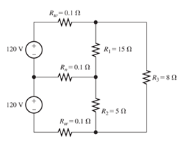
Figure P2.75
Expert Solution & Answer

Trending nowThis is a popular solution!

Students have asked these similar questions
Refer to the circuit on the right.
VEB = 0.7 V, when the BE junction is conducting.
VECsat = 0.2 V
B
Vref = 2.2 V
(Use two decimal places.)
= ∞
VREF
IL
+5 V
R
LOAD
Figure 2
a. What should be the value of R in ohms if IL is to be maintained at 146 mA under
changing load conditions?
b.
In order to maintain this load current, what should be the maximum allowable load
resistance in ohms?
Basic Electrical EngineeringDraw symbols of electrical components. Note: You may use both IEC and NEMA symbols.
- Conductors crossing but not connected- Conductors crossing and connected
- DC source other than battery- DC generator- AC voltage source- Ideal current source- Ideal Voltage Source- Current Controlled Current Source- Current Controlled Voltage Source- Voltage Controlled Current Source
- Voltage Controlled Voltage Source
For the series-parallel arrangement shown in the Figure below, find (a) the supply current, (b) the current flowing through each resistor and (c) the p.d. across each resistor (d). power dissipated by each resistor.
Chapter 2 Solutions
EBK ELECTRICAL ENGINEERING
Ch. 2 - Reduce each of the networks shown in Figure P2.1...Ch. 2 - A 4- resistance is in series with the parallel...Ch. 2 - Find the equivalent resistance looking into...Ch. 2 - Suppose that we need a resistance of 1.5 k and...Ch. 2 - Find the equivalent resistance between terminals a...Ch. 2 - Find the equivalent resistance between terminals a...Ch. 2 - What resistance in parallel with 120 results in...Ch. 2 - Determine the resistance between terminals a and b...Ch. 2 - Two resistances having values of R and 2R are in...Ch. 2 - A network connected between terminals a and b...
Ch. 2 - Two resistances R1 and R2 are connected in...Ch. 2 - Find the equivalent resistance for the infinite...Ch. 2 - If we connect n 1000- resistances in parallel,...Ch. 2 - The heating element of an electric cook top has...Ch. 2 - We are designing an electric space heater to...Ch. 2 - Sometimes, we can use symmetry considerations to...Ch. 2 - The equivalent resistance between terminals a and...Ch. 2 - Three conductances G1 G2, and G3 are in series....Ch. 2 - Most sources of electrical power behave as...Ch. 2 - The resistance for the network shown in Figure...Ch. 2 - Often, we encounter delta-connected loads such as...Ch. 2 - What are the steps in solving a circuit by network...Ch. 2 - Find the values of i1 and i2 in Figure P2.23....Ch. 2 - Find the voltages v1 and v2 for the circuit shown...Ch. 2 - Find the values of v and i in Figure P2.25. Figure...Ch. 2 - Consider the circuit shown in Figure P2.24....Ch. 2 - Find the voltage v and the currents i1 and 12 for...Ch. 2 - Find the values of vs, v1, and i2 in Figure P2.28....Ch. 2 - Find the values of i1 and i2 in Figure P2.29....Ch. 2 - Consider the cirrcuit shown in Figure P2.30 Find...Ch. 2 - Solve for the values of i1, i2, and the powers for...Ch. 2 - The 12-V source in Figure P2.32 is delivering 36...Ch. 2 - Refer to the circuit shown in Figure P2.33. With...Ch. 2 - Find the values of i1 and i2 in Figure P2.34. Find...Ch. 2 - Find the values of i1 and i2 in Figure P2.35...Ch. 2 - Use the voltage-division principle to calculate...Ch. 2 - Use the current-division principle to calculate i1...Ch. 2 - Use the voltage-division principle to calculate...Ch. 2 - Use the current-division principle to calculate...Ch. 2 - Suppose we need to design a voltage-divider...Ch. 2 - A source supplies 120 V to the series combination...Ch. 2 - We have a 60- resistance, a 20- resistance, and...Ch. 2 - A worker is standing on a wet concrete floor,...Ch. 2 - Suppose we have a load that absorbs power and...Ch. 2 - We have a load resistance of 50 that we wish to...Ch. 2 - We have a load resistance of 1 k that we wish to...Ch. 2 - The circuit of Figure P2.47 is similar to networks...Ch. 2 - Write equations and solve for the node voltages...Ch. 2 - Solve for the node voltages shown in Figure P2.49....Ch. 2 - Solve for the node voltages shown in Figure P2.50....Ch. 2 - Given R1=4 , R2=5 , R2=8 , R4=10 , R5=2 , and...Ch. 2 - Determine the value of i1 in Figure P2.52 using...Ch. 2 - Given R1=15 , R5=5 , R3=20 , R4=10 , R5=8 , R6=4 ,...Ch. 2 - In solving a network, what rule must you observe...Ch. 2 - Use the symbolic features of MATLAB to find an...Ch. 2 - Solve for the values of the node voltages shown in...Ch. 2 - Solve for the node voltages shown in Figure P2.57....Ch. 2 - Solve for the power delivered to the 8- ...Ch. 2 - Solve for the node voltages shown in Figure P2.59....Ch. 2 - Find the equivalent resistance looking into...Ch. 2 - Find the equivalent resistance looking into...Ch. 2 - Figure P2.62 shows an unusual voltage-divider...Ch. 2 - Solve for the node voltages in the circuit of...Ch. 2 - We have a cube with 1- resistances along each...Ch. 2 - Solve for the power delivered to the 15- resistor...Ch. 2 - Determine the value of v2 and the power delivered...Ch. 2 - Use mesh-current analysis to find the value of i1...Ch. 2 - Solve for the power delivered by the voltage...Ch. 2 - Use mesh-current analysis to find the value of v...Ch. 2 - Use mesh-current analysis to find the value of i3...Ch. 2 - Use mesh-current analysis to find the values of i1...Ch. 2 - Find the power delivered by the source and the...Ch. 2 - Use mesh-current analysis to find the values of i1...Ch. 2 - Use mesh-current analysis to find the values of i1...Ch. 2 - The circuit shown in Figure P2.75 is the dc...Ch. 2 - Use MATLAB and mesh-current analysis to determine...Ch. 2 - Connect a 1-V voltage source across terminals a...Ch. 2 - Connect a 1-V voltage source across the terminals...Ch. 2 - Use MATLAB to solve for the mesh currents in...Ch. 2 - Find the Thévenin and Norton equivalent circuits...Ch. 2 - We can model a certain battery as a voltage source...Ch. 2 - Find the Thévenin and Norton equivalent circuits...Ch. 2 - Find the Thévenin and Norton equivalent circuits...Ch. 2 - Find the Thévenin arid Norton equivalent circuits...Ch. 2 - An automotive battery has an open-circuit voltage...Ch. 2 - A certain two-terminal circuit has an open-circuit...Ch. 2 - If we measure the voltage at the terminals of a...Ch. 2 - Find the Thévenin and Norton equivalent circuits...Ch. 2 - Find the maximum power that can be delivered to a...Ch. 2 - Find the maximum power that can be delivered to a...Ch. 2 - Figure P2.91 shows a resistive load RL connected...Ch. 2 - Starling from the Norton equivalent circuit with a...Ch. 2 - A battery can be modeled by a voltage source Vt in...Ch. 2 - Use superposition to find the current i in Figure...Ch. 2 - Solve for is in Figure P2.49 by using...Ch. 2 - Solve the circuit shown in Figure P2.48 by using...Ch. 2 - Solve for i1 in Figure P2.34 by using...Ch. 2 - Another method of solving the circuit of Figure...Ch. 2 - Use the method of Problem P2.98 for the circuit of...Ch. 2 - Solve for the actual value of i6 for the circuit...Ch. 2 - Device A shown in Figure P2.101 has v=3i2 for i 0...Ch. 2 - The Wheatstone bridge shown in Figure 2.66 is...Ch. 2 - The Wheatstone bridge shown in Figure 2.66has...Ch. 2 - In theory, any values can be used for R1 and R3 in...Ch. 2 - Derive expressions for the Thévenin voltage and...Ch. 2 - Derive Equation 2.93 for the bridge circuit of...Ch. 2 - Prob. 2.107PCh. 2 - Explain what would happen if, in wiring the bridge...Ch. 2 - Match each entry in Table T2.1(a) with the best...Ch. 2 - Consider the circuit of Figure T2.2 with vs=96V ,...Ch. 2 - Write MATLAB code to solve for the node voltages...Ch. 2 - Write a set of equations that can be used to solve...Ch. 2 - Determine the Thévenin and Norton equivalent...Ch. 2 - According to the superposition principle, what...Ch. 2 - Determine the equivalent resistance between...Ch. 2 - Transform the 2-A current source and 6- ...
Knowledge Booster


Learn more about
Need a deep-dive on the concept behind this application? Look no further. Learn more about this topic, electrical-engineering and related others by exploring similar questions and additional content below.Similar questions
- Draw AC and DC equivalent circuit for the circuit given in Figure 4arrow_forwardB. Define ( resistance, reactance, impedance. rks rksarrow_forwarda) Graphically show the differences between alternating current voltage (A.C) and direct current voltage (D.C). What are the advantages of A.C compared to D.C?arrow_forward
- How do I solve this using Kirchoff's Voltage Law?arrow_forwardQ1. a) An SCR based AC power controller circuit is given in Figure 1. The circuit connects a 240V 50Hz AC source vi to a resistive load with resistance of 100. If the delay angle is a-15°, draw the waveforms of the load voltage Vo, and the voltage across SCR2. Calculate the power supplied to the load. + Vi Va + 2 SCR2 H₁₁ SCR₁ Figure 1 SCR based AC power control circuit Va + 2 io b) Figure 2 is a single phase 2-level voltage source converter (VSC) with a DC voltage Vd-200V. A PWM scheme, by comparing a reference value with a 10kHz triangle waveform, is used to control the switches S₁ and S2. The modulation index of the PWM is m=0.8. With the aid of graphs explain how pulse signals for the switches are generated, sketch the output voltage Vo, determine the duty cycle, and calculate the average output voltage. + Vo + Vo √ ₂ == Figure 2 A single phase VSCarrow_forwardConsider a typical electrical circuit system shown in Figure 2. The circuit consisting of two resisters value R, and R2 (ohm), a capacitance of value C (farad) and an inductance of value L (henry). The input is the supplied voltage V, and the output voltage is Vo- viz R1 Vi R2 Vo Figure 2 (1). Apply Kirchhoffs voltage law or other principles to derive the input-output dynamic model equation. (i). Apply Laplace Transform to determine the model transfer function for the electrical system. (i). Estimate the transfer function for the following R; = (ohm) and R2 = (ohm), L = (henry), and C = (farad) values. Task 4 R, (ohm) R: (ohm) C (farad) (henry) Note: Refer the Table for R1, R2, C and L values. 27 13 24 4 lellllarrow_forward
- In order to obtain the DC operating points for the circuit in the figure, please redraw the circuit with appropriate changes and explain.arrow_forwardIf a circuit has two equal parallel resistances connected to a 150V DC power source , then the P.D. exist between the mid-point of one resistance and a point that is one-third from the other resistance equal to -----arrow_forwardQuestion 3: A very simple model for the distribution of clectricity to a typical home is shown in the figure below. Some of components labeled a, b, c, d, c, f, g and h represent the electrical source to the home, some represent the wires that carry the electrical current from the source to the devices in the home requiring electrical power, some represent lamps, televisions, hair dryers and other devices that require power. Assume you are an engineer in charge of a project and one of your subordinate engineers reports that the interconnection in the figure does not pass the power check. The data for the interconnection are given in the table below. Is the subordinate correer? Explain your answer. If the subordinate is correct, find the error in the data. Explain your answer clearly. Based on your answer identify that which label(s) used for the electrical source, wires or other devices. a e harrow_forward
- lo R1 CR2 V alx ........ Figure Q2(b) : Two Closed Loops Circuit (i) Explain the steps required in supermesh analysis for Figure Q2(b). (ii) Determine the mesh currents using the Kirchhoff's Current Law (KCL) and Kirchhoff's Voltage Law (KVL) for Figure Q2(b).arrow_forwardFor the circuit below, determine the resistor current. The source is 8 volts, the Zener potential is 5.2 volts and the resistor is 5k ohms.arrow_forwardWhat will happen to the value of the impedance if the resistance will be increased or decreased? Explain...arrow_forward
arrow_back_ios
SEE MORE QUESTIONS
arrow_forward_ios
Recommended textbooks for you
 Power System Analysis and Design (MindTap Course ...Electrical EngineeringISBN:9781305632134Author:J. Duncan Glover, Thomas Overbye, Mulukutla S. SarmaPublisher:Cengage Learning
Power System Analysis and Design (MindTap Course ...
Electrical Engineering
ISBN:9781305632134
Author:J. Duncan Glover, Thomas Overbye, Mulukutla S. Sarma
Publisher:Cengage Learning
How do Solar cells work?; Author: Lesics;https://www.youtube.com/watch?v=L_q6LRgKpTw;License: Standard Youtube License