
Concept explainers
Videos
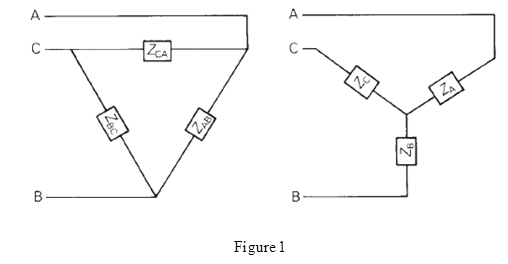
Figure 2.33 gives the general
Want to see the full answer?
Check out a sample textbook solution
Chapter 2 Solutions
POWER SYSTEM ANALYSIS+DESIGN-EBK >I<


- Impedances Z2 and Z3 in parallel are in series with impedance Z1 across a 100 V, 50 Hz ac supply. Z1 =6.25 + j1.25 ohm; Z2 = 5+ j0 ohm and Z3 = 5-jXc ohm. Determine the value of capacitance of Xc such that the total curent of the circuit will be in phase with the total voltage. When is then the circuit current and power.arrow_forwardDraw Wye- Delta three phase transformers connection ( no-load and full-load) in Lt-spicearrow_forwardDetermine the load currents at 2 0, 14 N, 4 0 and 100 Q using Superposition theorem. 2n3 TOI: 1)5A 59arrow_forward
- The Figure shows a balanced Y-A 3Ø circuit. The phase voltages of the Y-connected source are V, = 11020°, V, = 1102 - 120° and V. = 1102120°, Volts. The line impdedances are Z,=10+j5 Q each. The impedances of the A-connected load are ZA = 75+j255 N each. Determine: Line Currents, Phase Currents (load), Power drawn by the load. Ve ZA Vbarrow_forwardFor the single-phase circuit shown in Figure 2.22, I5 10/08A. (a) Compute the phasors I1, I2, and V. (b) Draw a phasor diagram showing I, I1 I2, and Varrow_forwardThe one-line diagram of a three-phase power system is shown in the above figure. The line impedances are in per- unit on a 100-MVA base, and the line admittances are neglected. ' qu V = 1.05200 0.01+ j0.025 300 + j200 MVA 3 0.015 + j0.035 150 MW 200 + j150 MVA 0.01 + j0.03 |V = 1.03 The admittance matrix (Y_bus)? The bus power in per-unit?arrow_forward
- A three-phase system has balanced conditions so that the per-phase circuit representation can be used as shown in Figure 1 Select the turns ratio of the step-up and step-down transformers that the system operates with an efficiency greater than 99 percent. Moreover, find the complex power (received or given) of all components in the circuit and the V1 and V2 voltages. The load voltage is specified as 4 kV rms, and the load impedance is 4/3 ohm. ..arrow_forwardUsing Figure 1, Vs 50V-15 339 Hz R1 $1100 R2 100 www XL1 320 HH XC1 Figure 1 700 R3 600 13 R4 400 XL2 1902 XL3 450 XC2 650 a. Determine the total circuit impedance, ZT. b. Calculate current IT. c. Calculate currents I, and I3. State the value of these currents in both rectangular and polar form. d. For each of the currents determined in part c, answer the following: Is the current leading, lagging, or in phase with the source voltage. e. Use the voltage-divider rule to determine the voltages across XL1 and Xc2.arrow_forwardQ1. A balanced 3 phase Y-Y connected circuit with positive sequence is as shown in the figure. 0.62 j20 1.20 jóN 68 N j46N 200 20° 200 2-120° IN 0.6N j2N m 1.20 j6 N 68 N j46 N b | 200 2120° 0.62 j2N 1.20 j6N 68 N j46 N a) Construct a single-phase equivalent circuit of the 3-phase system. b) Calculate the line currents: laa, IbB and Icc. c) Calculate the phase voltages at the load terminals: VAN, VBN and VCN. d) Calculate the line voltages at the load terminals: VAB, VBC and VCA.arrow_forward
- In a balanced Y-Y circuit shown in Figure 5, the magnitude of the phase voltage at the source is Vp = 2520 V (rms) and Van = 252020° V (rms). The load impedance is Zy = 135 + j55 Q per phase and the wire impedance is Zw=85 + j65 per phase. All the voltages and currents are in rms in this problem. (a) Find the phasors for line currents IA, IB, Ic in rms. (b) Find the load voltage VAN = IAZY. Also find VBN, and VCN. (c) Find the line voltages VAB, VBC, VCA at the load. (d) Find the complex power SL of the load. ZW ZY Van a A IA ZW ZY Vbn b В IB N ZW ZY Vcn IC Figure 5arrow_forwardV:.. H.W. .mp4 www.DANDICAMCO H.W. 1 Poly-phase Systems A three phase, four-wire, 208 volt, CBA system has a wyeconnected load with Z, = 60°, 2, = 6/30° and Ze = 5/45°. Obtain the three line currents and the neutral current(in a polar form) after finding O2 and 03. A' 120/03 1002 B- 120/150arrow_forward20) Two AC generators A and B are in Parallel. Each generator has an emf of 1000V per phase and in phase, the phase impedance are ZA = 0.1+j2 ohms, ZB = 0.2+j3.2 ohms respectively. If the common load has an impedance of (2+j1) ohms per phase, solve the voltage per phase at the loadarrow_forward
 Power System Analysis and Design (MindTap Course ...Electrical EngineeringISBN:9781305632134Author:J. Duncan Glover, Thomas Overbye, Mulukutla S. SarmaPublisher:Cengage Learning