Concept explainers
Videos
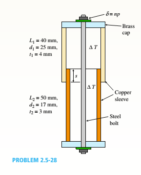
Consider the sleeve made From two copper tubes joined by tin-lead solder over distance s. The sleeve has brass caps at both ends that are held in place by a steel bolt and washer with the nut turned just snug at the outset. Then, two "loadings" are applied: a = 1/2 turn applied to the nut; at the same time, the internal temperature is raised by ?T = 30°C.
(a) Find the forces in the sleeve and boll, Psand PB, due to both the priestess in the bolt and the temperature increase. For copper, use EI= 120 GPa and ac= 17 × W+C; for steel, use E, = 200 GPa and a, = 12 × 10-6/°C. The pitch of the boll threads is p = 1.0 mm. Assume s = 26 mm and bolt diameter dB= 5 mm.
(b) Find the required length of the solder joint, s, if shear stress in the sweated joint cannot exceed the allowable shear stress t ™ 18.5 MPa.
(c) What is the final elongation of the entire assemblage due to both temperature change A T and the initial prestress in the bolt?
(a)
The force on the sleeve and force on the blot.
Answer to Problem 2.5.28P
The force on the sleeve is =
The force on the bolt is =
Explanation of Solution
Given information:
The length of the copper sleeve is
Write the expression for area of bolt.
Here, area of the bolt is
Write the expression for the area of the copper sleeve.
Here, area of the copper sleeve is
Write the expression for the area of steel bolt.
Here, area of steel bolt is
Write the expression for the elongation in bolt.
Here, elongation in bolt is
Write the expression for elongation.
Here, elongation is
Write the compatibility Equation for elongation.
Calculation:
Substitute
Substitute
Substitute
Substitute
Substitute
Substitute
Since
Conclusion:
The force on the sleeve is
The force on the bolt is
(b)
The required length of the joint.
Answer to Problem 2.5.28P
The required length of the joint is
Explanation of Solution
Given information:
The length of the copper sleeve is
Write the expression for area.
Here, area of sleeve is
Write the expression for allowable shear stress.
Here, allowable shear stress is
Calculation:
Substitute
Substitute
Conclusion:
The required length of joint is
(c)
The final displacement.
Answer to Problem 2.5.28P
The final displacement is
Explanation of Solution
Given information:
The length of the copper sleeve is
Write the expression for displacement in bolt.
Here, the displacement in bolt is
Write the expression for displacement in sleeve.
Here, the displacement in sleeve is
Write the expression for final elongation.
Here, the final elongation is
Calculation:
Substitute
Substitute
Substitute
Conclusion:
The final displacement is =
Want to see more full solutions like this?
Chapter 2 Solutions
Mechanics of Materials - Text Only (Looseleaf)


- A two-story building has steel columns AB in the first floor and BC in the second floor, as shown in the figure. The roof load P:equals 400 KN, and the second-floor load P-, equals 720 kN. Each column has a length L = 3.75 m. The cross-sectional areas of the first- and second-floor columns are 11,000 mm" and 3900 mm", respectively. (a) Assuming that E = 206 GPa. determine the total shortenings aof the two columns due to the combined action of the loads Ptand P,. (b) How much additional load P0can be placed at t he top of t he column (point C) if t he total shortening: SACis not to exceed 4.0 mm?arrow_forwardA hollow circular tube T of a length L = 15 in. is uniformly compressed by a force P acting through a rigid plate (see figure). The outside and inside diameters of the tube are 3.0 and 2.75 in., respectively. A concentric solid circular bar B of 1.5 in. diameter is mounted inside the lube. When no load is present, there is a clearance c = 0.0I0 in. between the bar B and the rigid plate. Both bar and tube are made of steel having an c[autoplastic stress-strain diagram with E = 29 X LO3 ksi and err= 36 ksi. (a) Determine the yield load Pt- and the corresponding shortening 3yof the lube. (b) Determine the plastic load Ppand the corresponding shortening Spof the tube. (c) Construct a load-displacement diagram showing the load Pas ordinate and the shortening 5 of the tube as abscissa. Hint: The load-displacement diagram is not a single straight line in the region 0 ^ P ^ Prarrow_forward(a) Solve part (a) of the preceding problem if the pressure is 8.5 psi, the diameter is 10 in., the wall thickness is 0,05 in., the modulus of elasticity is 200 psi, and Poisson's ratio is 0.48. (b) If the strain must be limited to 1.01, find the maximum acceptable inflation pressurearrow_forward
- A rubber ball (sec figure) is inflated to a pressure of 65 kPa. At that pressure, the diameter of the ball is 240 mm and the wall thickness is 1.25 mm. The rubber has a modulus of elasticity E = 3,7 MPa and Poisson's ratio v = 0.48. (a) Determine the maximum stress and strain in the ball, (b) If the strain must be limited to 0.425, Find the minimum required wall thickness of the ball.arrow_forward• - 3 A rectangular plate in biaxial stress (see figure) is subjected to normal stresses u = 67 MPa (tension) and s = -23 MPa (compression). The plate has dimensions 400 X 550 X 20 mm and is made of steel with E = 200 GPa and v = 0.30. (a) Determine the maximum in-plane shear strain ?max in the plate. (b) Determine the change ?t in the thickness of the plate. (c) Determine the change ?t in the volume of the plate.arrow_forwardRectangular bars of copper and aluminum are held by pins at their ends, as shown in the figure. Thin spacers provide a separation between the bars. The copper bars have cross-sectional dimensions 0.5 in. × 2.0 in., and the aluminum bar has dimensions 1.0 in. × 2.0 in. Determine the shear stress in the 7/16-in. diameter pins if the temperature is raised by 100°F. (For copper, Et= 18,000 ksi and ac = 9.5 × 10⁻⁶/?; for aluminum, Ea= 10,000 ksi and aa= 13 × 10-6/?.) Suggestion: Use the results of Example 2-10arrow_forward
- A pressurized cylindrical tank with flat ends is loaded by torques T and tensile forces P (sec figure), The tank has a radius of r = 125 mm and wall thickness t = 6.5 mm. The internal pressure p = 7.25 MPa and the torque T = 850 N m. (a) What is the maximum permissible value of the forces P if the allowable tensile stress in the wall of the cylinder is 160 MPa? (b) If forces P = 400 kN, what is the maximum acceptable internal pressure in the tank?arrow_forwardA sliding collar of weight W = 150 lb falls From a height h = 2.0 in. onto a flange at the bottom of a slender vertical rod (see figure). The rod has a length L = 4.0 ft, cross-sectional area A = 0.75 in2, and modulus of elasticity E = 30 X 106 psi. Calculate the following quantities: (a) the maximum downward displacement of the flange, (b) the maximum tensile stress in the rod, and (c) the impact factor.arrow_forwardSolve the preceding problem if the diameter is 480 mm, the pressure is 20 MPa, the yield stress in tension is 975 MPa, the yield stress in shear is 460 MPa, the factor of safety is 2,75, the modulus of elasticity is 210 GPa, Poissorfs ratio is 0.28, and the normal strain must not exceed 1190 x 10" . For part (b), assume that the tank thickness is 8 mm and the measured normal strain is 990 x 10~ .arrow_forward
- A solid circular bar of steel (G = 78 GPa) transmits a torque T = 360 N - m. The allowable stresses in tension, compression, and shear arc 90 MPa, 70 MPa, and 40 MPa, respectively. Also, the allowable tensile strain is 220 x 10-6, Determine the minimum required diameter d of the bar, If the bar diameter d = 40 mm, what is Tmax?arrow_forward-21 Plastic bar AB of rectangular cross section (6 = 0.75 in. and h = 1.5 in.) and length L = 2 Ft is Fixed at A and has a spring support (Ar = 18 kips/in.) at C (see figure). Initially, the bar and spring have no stress. When the temperature of the bar is raised hy foot. the compressive stress on an inclined plane pq at Lq = 1.5 Ft becomes 950 psi. Assume the spring is massless and is unaffected by the temperature change. Let a = 55 × l0-6p and E = 400 ksi. (a) What is the shear stresst9 on plane pq? What is angle 07 =1 Draw a stress element oriented to plane pq, and show the stresses acting on all laces of this element. (c) If the allowable normal stress is ± 1000 psi and the allowable shear stress is ±560 psi, what is the maximum permissible value of spring constant k if the allowable stress values in the bar are not to be exceeded? (d) What is the maximum permissible length L of the bar if the allowable stress values in the bar are not be exceeded? (Assume £ = IB kips/in.) (e) What is the maximum permissible temperature increase (A7") in the bar if the allowable stress values in the bar are not to be exceeded? (Assume L = 2 ft and k = L& kips/inarrow_forwardA thin-walled circular tube and a solid circular bar of the same material (see figure) are subjected to torsion. The tube and bar have the same cross-sectional area and the same length. What is the ratio of the strain energy U1in the tube to the strain energy U2in the solid bar if the maximum shear stresses are the same in both cases? (For the tube, use the approximate theory for thin-walled bars.)arrow_forward
 Mechanics of Materials (MindTap Course List)Mechanical EngineeringISBN:9781337093347Author:Barry J. Goodno, James M. GerePublisher:Cengage Learning