Videos
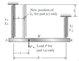
A uniform bar AB of weight W = 25 N is supported by two springs, as shown in the figure. The spring on the left has a stiffness k[= 300 N/m and natural length Lt=250 mm. The corresponding quantities for the spring on the right are k2= 400 N/m and L^ = 200 mm. The distance between the springs is L = 350 mm, and the spring on the right is suspended from a support that is a distance it = SO mm below the point of support for the spring on the left. Neglect the weight of the springs.
(a) At what distance x from the left-hand spring (figure part a) should a load P = 18 N be placed in order to bring the bar to a horizontal position? (b) If P is now removed, what new value of k{is required so that the bar (figure part a) will hang in a horizontal position underweight If?
(c) If P is removed and kt= 300 N/m. what distance b should spring ktbe moved to the right so that the bar (figure part a) will hang in a horizontal position under weight II"?
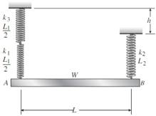
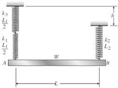
(d) If the spring on the left is now replaced by two springs in series (kt= 300 N/m, kt) with overall natural length Lt= 250 mm (see figure part b). what value of k; is required so that the bar will hang in a horizontal position under weight IF?
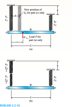
(a)
Location of load
Answer to Problem 2.2.16P
Location of load
Explanation of Solution
Given:
 Weight,
Spring stiffness on left and right,
Natural lengths of both springs,
Distance between the springs,
Load,
Distance from support,
We have to use statics to get forces in both springs.
Now, we use constraint equation to define horizontal position, then solve for location
We are required to substitute expressions for
(b)
New value of spring constant
Answer to Problem 2.2.16P
New value of spring constant
Explanation of Solution
Given:
 Weight,
Spring stiffness on left and right,
Natural lengths of both springs,
Distance between the springs,
Load,
Distance from support,
New value of spring constant
Now,
Since,
Same constant equation as above but now:
Now, solve for
(c)
Distance moved by spring
Answer to Problem 2.2.16P
Distance moved by spring
Explanation of Solution
Given:
New position for
Weight,
Spring stiffness on left and right,
Natural lengths of both springs.
Distance between the springs,
Load,
Distance from support,
Use
But relocate spring,
So, that bar ends up in horizontal position underweight
Statics are as follows:
Now, we have the constraint equation − substitute above expression for
Use the following data:
Spring stiffness on left and right.
Natural lengths of both springs:
Distance between the springs.
By substituting
(d)
Value of
Answer to Problem 2.2.16P
The required value is,
Explanation of Solution
Given:
Weight,
Spring stiffness on left and right,
Natural lengths of both springs,
Distance between the springs:
Load,
Distance from support,
Value of
New constraint equation is as follows:
Want to see more full solutions like this?
Chapter 2 Solutions
Mechanics of Materials - Text Only (Looseleaf)


- A round bar ABC of length 2L (see figure) rotates about an axis through the midpoint C with constant angular speed w (radians per second). The material of the bar has weight density y. (a) Derive a formula for the tensile stress a’ in the bar as a function of the distance x from the midpoint C. (b) What is the maximum tensile stress a max?arrow_forwardA sliding collar of weight W = 150 lb falls From a height h = 2.0 in. onto a flange at the bottom of a slender vertical rod (see figure). The rod has a length L = 4.0 ft, cross-sectional area A = 0.75 in2, and modulus of elasticity E = 30 X 106 psi. Calculate the following quantities: (a) the maximum downward displacement of the flange, (b) the maximum tensile stress in the rod, and (c) the impact factor.arrow_forwardA hollow circular pipe (see figure} support s a load P that is uniformly distributed around a cap plate at the top of the lower pipe. The inner and outer diameters of the upper and lower parts of the pipe are d1= 50 mm, d2= 60 mm, rf3 = 57 mm, and d1= 64 mm, respectively. Pipe lengths are Lt= 2 m and L, = 3 m. Neglect the self-weight of the pipes. Assume that cap plate thickness is small compared to I, and E,. Let E = 110 MPa. (a) If the tensile stress in the upper part is d = 10.5 MPa. what is load PI Also, what are reactions ft, at the upper support and R-, at the lower support? What is the stress ar(MPa) in the lower part? (b) Find displacement S(mm) at the cap plate. Plot the axial force diagram (AFD) [Ar(.f)] and axial displacement diagram (ADD)[5(.t)]. (c) Add the uniformly distributed load q along the censorial axis of pipe segment 2. Find q (kN/m) so that It, = 0. Assume that load P from part (a) is also applied.arrow_forward
- -21 Plastic bar AB of rectangular cross section (6 = 0.75 in. and h = 1.5 in.) and length L = 2 Ft is Fixed at A and has a spring support (Ar = 18 kips/in.) at C (see figure). Initially, the bar and spring have no stress. When the temperature of the bar is raised hy foot. the compressive stress on an inclined plane pq at Lq = 1.5 Ft becomes 950 psi. Assume the spring is massless and is unaffected by the temperature change. Let a = 55 × l0-6p and E = 400 ksi. (a) What is the shear stresst9 on plane pq? What is angle 07 =1 Draw a stress element oriented to plane pq, and show the stresses acting on all laces of this element. (c) If the allowable normal stress is ± 1000 psi and the allowable shear stress is ±560 psi, what is the maximum permissible value of spring constant k if the allowable stress values in the bar are not to be exceeded? (d) What is the maximum permissible length L of the bar if the allowable stress values in the bar are not be exceeded? (Assume £ = IB kips/in.) (e) What is the maximum permissible temperature increase (A7") in the bar if the allowable stress values in the bar are not to be exceeded? (Assume L = 2 ft and k = L& kips/inarrow_forwardA rigid bar AB having a mass M = 1.0 kg and length L = 0.5 m is hinged at end A and supported at end B by a nylon cord BC (see figure). The record has cross-sectional area A = 30 mm2. length b = 0.25 m. and modulus of elasticity E = 2.1 GPa. If the bar is raised to its maximum height and then released, what is the maximum stress in the cord?arrow_forwardThe L-shaped arm ABCD shown in the figure lies in a vertical plane and pivots about a horizontal pin at A. The arm has a constant cross-sectional area and total weight W. A vertical spring of stiffness k supports the arm at point B. (a) Obtain a formula for the elongation of the spring due to the weight of the arm. (b) Repeat part (a) if the pin support at A is moved to D.arrow_forward
- By what distance h does the cage shown in the figure move downward when the weight W is placed inside it? (See the figure.) Consider only the effects of the stretching of the cable, which has axial rigidity EA = 10,700 kN. The pulley at A has a diameter da= 300 mm and the pulley at B has a diameter dB= 150 mm. Also, the distance L1= 4.6 m, the distance L2=10.5 m, and the weight W = 22 kN. Note: When calculating the length of the cable. include the parts of the cable that go around the pulley sat A and B.arrow_forward-7 The truss A BC Shawn in the figure supports a horizontal load P1= 300 lb and a vertical load P2= 9001b. Both bars have a cross-sectional area A = 2.4 in2 and are made of steel with E = 30 X 106 psi. (a) Determine the strain energy U1of the truss when the load P1acts alone (P2= 0). (b) Determine the strain energy U2when the load P2acts alone (P1= 0). (c) Determine the strain energy U3when both loads act simultaneously.arrow_forwardA bar ABC revolves in a horizontal plane about a vertical axis at the midpoint C (see figure). The bar, which has a length 2L and crass-sectional area A, revolves at constant angular speed at. Each half of the bar (AC and BC) has a weight W, and supports a weight W2at its end. Derive the following formula for the elongation of one-half of the bar (that is. the elongation of either AC ar BC). =L223gEA(w1+3w2) in which E is t he modulus of elasticity of the material of the bar and g is the acceleration of gravity.arrow_forward
- A hollow circular tube T of a length L = 15 in. is uniformly compressed by a force P acting through a rigid plate (see figure). The outside and inside diameters of the tube are 3.0 and 2.75 in., respectively. A concentric solid circular bar B of 1.5 in. diameter is mounted inside the lube. When no load is present, there is a clearance c = 0.0I0 in. between the bar B and the rigid plate. Both bar and tube are made of steel having an c[autoplastic stress-strain diagram with E = 29 X LO3 ksi and err= 36 ksi. (a) Determine the yield load Pt- and the corresponding shortening 3yof the lube. (b) Determine the plastic load Ppand the corresponding shortening Spof the tube. (c) Construct a load-displacement diagram showing the load Pas ordinate and the shortening 5 of the tube as abscissa. Hint: The load-displacement diagram is not a single straight line in the region 0 ^ P ^ Prarrow_forwardTwo pipe columns (AB, FC) are pin-connected to a rigid beam (BCD), as shown in the figure. Each pipe column has a modulus of E, but heights (L1or L2) and outer diameters (d1or different for each column. Assume the inner diameter of each column is 3/4 of outer diameter. Uniformly distributed downward load q = 2PIL is applied over a distance of 3L/4 along BC, and concentrated load PIA is applied downward at D. (a) Derive a formula for the displacementarrow_forwardA pressurized cylindrical tank with flat ends is loaded by torques T and tensile forces P (sec figure), The tank has a radius of r = 125 mm and wall thickness t = 6.5 mm. The internal pressure p = 7.25 MPa and the torque T = 850 N m. (a) What is the maximum permissible value of the forces P if the allowable tensile stress in the wall of the cylinder is 160 MPa? (b) If forces P = 400 kN, what is the maximum acceptable internal pressure in the tank?arrow_forward
 Mechanics of Materials (MindTap Course List)Mechanical EngineeringISBN:9781337093347Author:Barry J. Goodno, James M. GerePublisher:Cengage Learning