
Videos
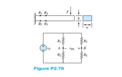
Figure P2.79 shows an aluminum cantilevered beam loaded by the force F. Strain gauges
Want to see the full answer?
Check out a sample textbook solution
Chapter 2 Solutions
Principles and Applications of Electrical Engineering


- A 30-volt electromotive force is applied to an ??-series circuit in which the inductance is 0.1 henry and the resistance is 50 ohms. Find the current ?(?) if ?(0) = 0. Determine the current as ? → ∞.arrow_forwardThe figure of merit which describes the overall behavior of the wire under stress isdetermined from?Select onea elastic modulus b gauge resistancegauge factorastic factorarrow_forwardType your question here Let Q1 = 8 µC be located at P1(2, 5, 8) while Q2 = -5 µC is at P2(6, 15, 8). Let €= €0. (a) Find F2, the force on Q2. (b) Find the coor- dinates of P3 if a charge Q3 experiences a total force F3 = 0 at P3.arrow_forward
- The figure of merit which describes the overall behavior of the wire under stress is deSelect one:O a. elastic factor O b. gauge factorO c. elastic modulusO d. gauge resistancearrow_forwarda rod of semiconducting meterial of length L = 2 m and cross-sectioanal area A=5mm2 lies along the x axis between x=0 and x=L. the meterial obeys Ohm's law, and its resistivity varies along the rod according to p=p0 (1-(x2/L2)) where p0=4,5 * 10-4 ohm*m. the end of the rod at x=0 is at a potential V0= 30 V greater than the end at x = L. a)what is the total resistance, in units of ohm, of the rod ? b)what is the current, in units of miliamperes in the rod? c)what is the electric potential, in units of Volt in the rod at x=L/2 ? d)what is the electric field magnitude E, in units of V/m, in the rod at x=L/2 ?arrow_forwardA DC current I flows in a long solenoidwith n coil-turns per unit length. Thecore is made of iron with permeability µ , and has a cross section area S.Determine the force acting on the coreif it is withdrawn to the position shownin figure.arrow_forward
- Find the equivalent resistance for the infinite network shown in Figure P2.12(a). Because of its form, this network is called a semi-infinite ladder. [Hint: If another section is added to the ladder as shown in Figure P2.12(b), the equivalent resistance is the same. Thus, working from Figure P2.12(b), we can write an expression for Req in terms of Req.Then, we can solve for Req.arrow_forwardFind the rolling force and its power. The weight of the car is 800 Kg The weight of each person is 75 Kg You may assume any missing parameters you need in the design appropriately (e.g., the rolling-resistance-power, air-resistance-power, the DC motor's parameters, ....etc)arrow_forwardWrite the application of super tension that have rating upto 33KV and what used for?arrow_forward
- A rectangular loop carrying current I2 is placed parallel to an infinitely long filamentarywire carrying current I1 as shown in figure. Show that the force experienced by the loopis given byarrow_forwardAn electric toothbrush has a base designed to hold the toothbrush handle when not in use. As shown, the handle has a cylindrical hole that fits loosely over a matching cylinder on the base. When the handle is placed on the base, a changing current in a solenoid inside the base cylinder induces a current in a coil inside the handle. This induced current charges the battery in the handle. We can model the base as a solenoid of length ℓ with NB turns (as shown), carrying a current i, and having a cross-sectional area A. The handle coil contains NH turns and completely surrounds the base coil. Find the mutual inductance of the system.arrow_forwardA 3-wire d.c. distributor, 250 m long, is supplied at end P at 500/250 V and is loaded as under : Positive side : 20 A, 150 m from P ; 30 A, 250 m from P Negative side : 24 A, 100 m from P ; 36 A, 220 m from P The resistance of each outer wire is 0·02 Ω per 100 m and the cross-section of the middle wire is one half that of the outer. Find the voltage across each load point.arrow_forward
 Power System Analysis and Design (MindTap Course ...Electrical EngineeringISBN:9781305632134Author:J. Duncan Glover, Thomas Overbye, Mulukutla S. SarmaPublisher:Cengage Learning
 Delmar's Standard Textbook Of ElectricityElectrical EngineeringISBN:9781337900348Author:Stephen L. HermanPublisher:Cengage Learning