
Concept explainers
Videos
For each of the circuits in Fig. 2.40, find the current I and compute the power absorbed by the resistor.
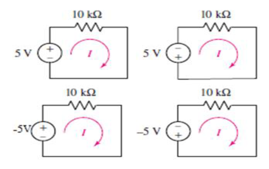
FIGURE 2.40
Find the current and power absorbed by resistor for each circuit in the given Figures.
Answer to Problem 54E
The current flowing in the circuit in Figure 1 is
The power absorbed by the resistor in Figure 1 is
The current flowing in the circuit in Figure 2 is
The power absorbed by the resistor in Figure 2 is
The current flowing in the circuit in Figure 3 is
The power absorbed by the resistor in Figure 3 is
The current flowing in the circuit in Figure 4 is
The power absorbed by the resistor in Figure 4 is
Explanation of Solution
Formula used:
The expression for current is as follows.
Here,
The expression for power absorbed by the resistor is as follows.
Here,
Calculation:
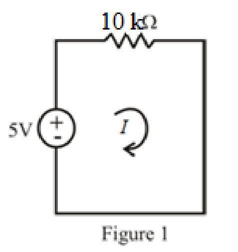
Refer to FIGURE 2.40(a) in the textbook.
The circuit diagram is redrawn as shown in Figure 1.
Substitute
Substitute
Refer to FIGURE 2.40(b) in the textbook.
The circuit diagram is redrawn as shown in Figure 2.
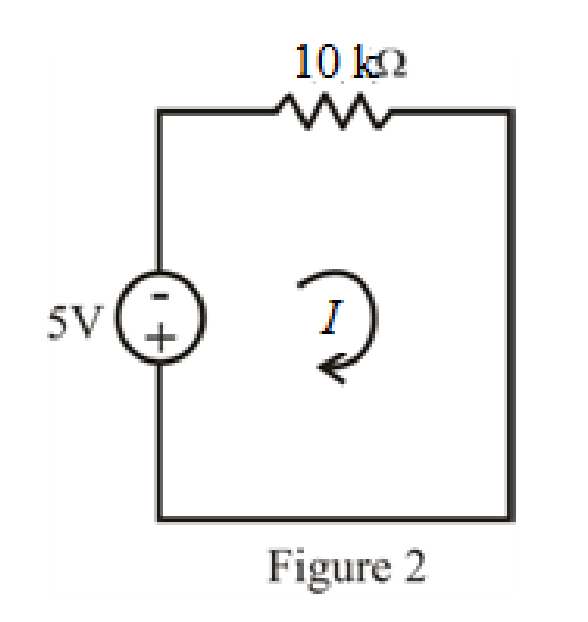
Refer to redrawn Figure 2
Substitute
Substitute
Refer to FIGURE 2.40(c) in the textbook.
The circuit diagram is redrawn as shown in Figure 3.
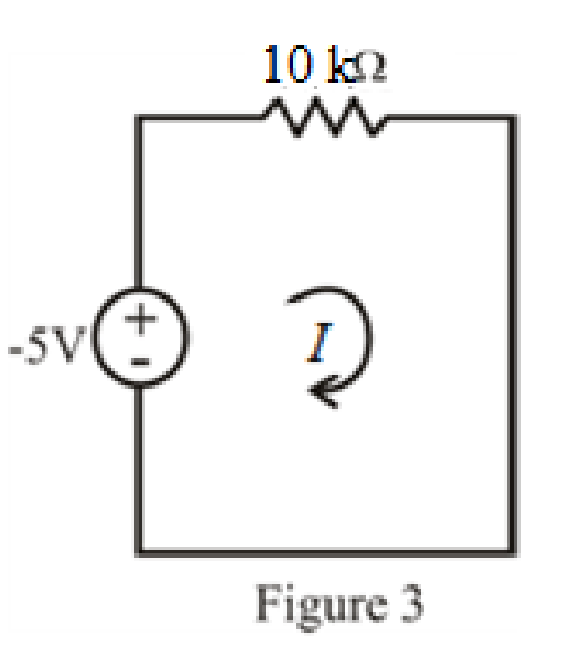
Refer to redrawn Figure 3.
Substitute
Substitute
Refer to FIGURE 2.40(d) in the textbook.
The circuit diagram is redrawn as shown in Figure 4.
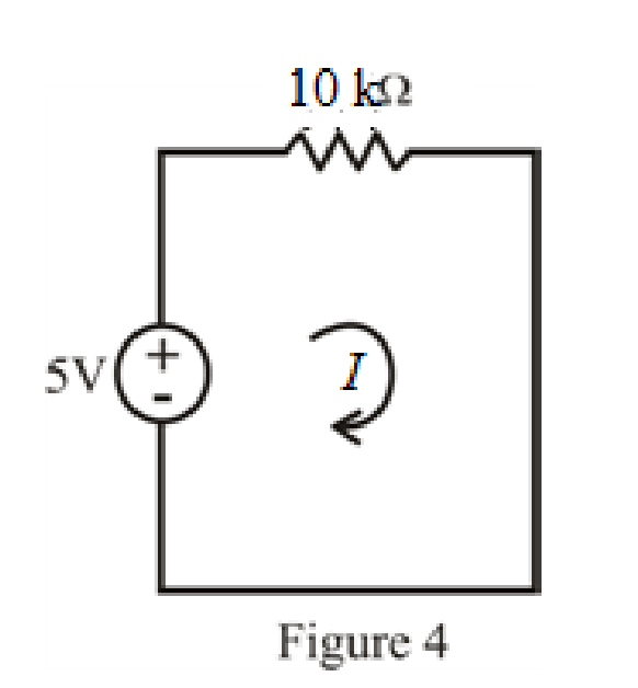
Refer to redrawn Figure 4.
Substitute
Substitute
Conclusion:
Thus, The current flowing in the circuit in Figure 1 is
The power absorbed by the resistor in Figure 1 is
The current flowing in the circuit in Figure 2 is
The power absorbed by the resistor in Figure 2 is
The current flowing in the circuit in Figure 3 is
The power absorbed by the resistor in Figure 3 is
The current flowing in the circuit in Figure 4 is
The power absorbed by the resistor in Figure 4 is
Want to see more full solutions like this?
Chapter 2 Solutions
ENGINEERING CIRCUIT ANALYSIS ACCESS >I<


- In Fig 2.41 the radiator will be replaced by the resistances. Only find the total power absorbed by the system in 2.42arrow_forwardQ5. A solar module with an area of 1.575 m2, gives a current at maximum power point of 9.25 A and voltage of 22.63 V. Find Maximum Power Point and efficiency of the module if power density is 1100 W/m2.arrow_forward#2write your solution pls plsarrow_forward
- determine the power dissipated when a curren of 10 mA flows through an appliance having a resistance of 8 K ohmiosarrow_forward1. A group of 5 x 10¹⁶ free electrons passed a point in a conductor in 20 s. Find the current flowing. 2. A water heater has a resistance of 5.5 Ω and draws a rated current of 40 A. Find the kWh consumed in a period of one month if the heater is in service on the average of 1.5 hours per day.arrow_forwardFind output power and efficiency of a Solar module if the voltage is 27.3 V, Current is 12.7A 2 and area of the module is 2.1 m . Power density of sunlight is 1000 W/m2arrow_forward
- Which of the following sources of energy can be used forever and in unlimited amounts? a. natural gas b. biofuels c. crude oil d. solararrow_forwardA walkman has 4 –AA batteries. The combination has a capacity of 200 watt-sec. How long will it take to discharge if walkman consumes 10mA at 6V?arrow_forwardAn electric heater having power rated 1000W connected to a 240V supply for 10minutes. a) Determine the heat energy produced of the electric heater. b) Calculate current taken from the supply. c) Find the resistance value of the heater element. d) Calculate the conductance of the heater element. e) Find the nett charge flowing in the heater element. f) Calculate the no. of free electron that represent for that amount charge obtained.arrow_forward
- A wire measuring 1.5 m3 has a resistance of 0.955 mW at 20°C; its length is 1.5 m and an area of 1.5 m2. Calculate the resistance of this wire at 20°C if the length is changed to 150 m and its area to 350 cm2arrow_forwardSolve the following problems below. Show complete solution. 1. A CFL or compact fluorescent lamp uses less energy that its equivalent incandescentbulb. How much will a person save of he uses a 30 W CFL instead of 100 W incandescentlamp for 7 hr in 30 days? Electricity is priced at 9.55 php / kW.hrarrow_forwardA flashlight has 4 – AA batteries. The combination has a capacity of 200 watt-sec. How long in mins will it take to discharge if the flashlight consumes 10 mA at 6 V?arrow_forward
 Introductory Circuit Analysis (13th Edition)Electrical EngineeringISBN:9780133923605Author:Robert L. BoylestadPublisher:PEARSON
 Delmar's Standard Textbook Of ElectricityElectrical EngineeringISBN:9781337900348Author:Stephen L. HermanPublisher:Cengage Learning
 Programmable Logic ControllersElectrical EngineeringISBN:9780073373843Author:Frank D. PetruzellaPublisher:McGraw-Hill Education
 Fundamentals of Electric CircuitsElectrical EngineeringISBN:9780078028229Author:Charles K Alexander, Matthew SadikuPublisher:McGraw-Hill Education
 Electric Circuits. (11th Edition)Electrical EngineeringISBN:9780134746968Author:James W. Nilsson, Susan RiedelPublisher:PEARSON
 Engineering ElectromagneticsElectrical EngineeringISBN:9780078028151Author:Hayt, William H. (william Hart), Jr, BUCK, John A.Publisher:Mcgraw-hill Education,