Concept explainers
Find the dead loads acting on the girder AE and beam CD.
Answer to Problem 6P
The dead load acting on the beam CD is
Dead load in Girder AE:
The dead load at C, A, and E are
The uniformly distributed load in the girder AE is
Explanation of Solution
Given information:
The thickness of the reinforced concrete slab is
The area of cross-section of the steel floor beam is
The area of cross-section of the steel girder is
The length, height, and thickness of the brick wall are
Calculation:
Show the floor systemof the building as shown in Figure 1.
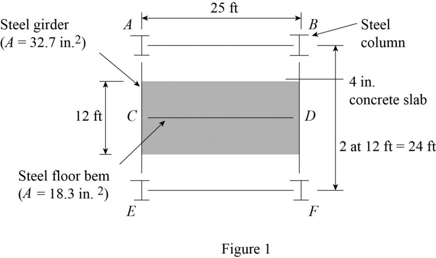
Refer Figure 1.
The tributary area of the beam CD is represented by the shaded region.
Tributary area of the beam CD:
The width of the tributary area of the beam CD is
The width of the tributary area of the beam CD is same as the length of the beam CD. Then,
The length of the tributary area of the beam CD is
The thickness of the concrete slab is
Refer Table 2.1 “Unit Weights of Construction Materials” in the text book.
The unit weight of the reinforced concrete is
The unit weight of the structural steel is
The unit weight of the brick wall is
Calculate the dead load per unit length of the beam CD as follows:
Concrete Slab:
Calculate the dead load of the concrete slab using the relation:
Substitute
Steel beam:
Calculate the dead load of the steel beam using the relation:
Substitute
Calculate the dead load of the brick wall using the relation:
Calculate the dead load of the beam CD as follows:
The dead load of
Show the dead load acting on the beam as shown in Figure 2.
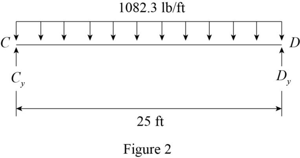
Refer Figure 2.
The reaction at C and D are denoted by
The dead load on the beam is symmetrical. Then,
Show the dead load acting on the beam as shown in Figure 3.
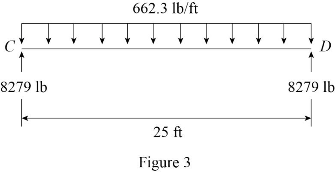
Refer Figure 3.
Thus, the dead load acting on the beam CD is
Show the floor system of the building as shown in Figure 4.
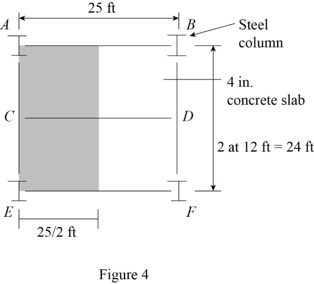
Refer Figure 4.
Tributary area of the girder AE:
The width of the tributary area of the girder AE is
The width of the tributary area of the girder AE is same as the length of the girder AE. Then,
The length of the tributary area of the girder AE is
The thickness of the reinforced concrete slab is
Calculate the dead load per unit length of the girder AE as follows:
Steel beam:
Calculate the dead load of the girder AE using the relation:
Substitute
Concentrated load at A and E.
Show the tributary area of column at A and E as shown in Figure 5.
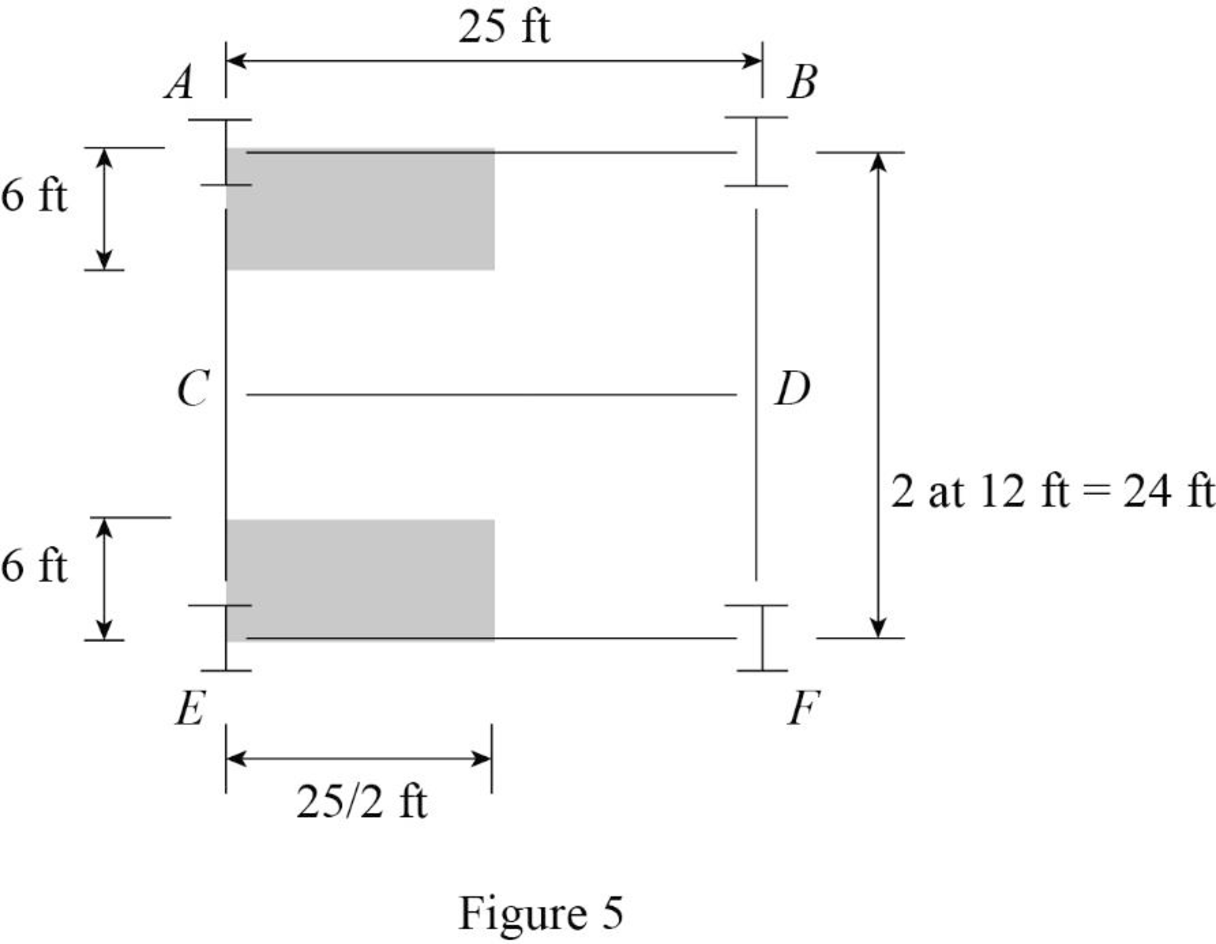
Refer Figure 5.
The tributary area of column at A and E are Equal.
The tributary area of column at A and E are
Calculate the concentrated load (P) at the column A and E the using the relation:
Substitute
Refer Figure 3.
The concentrated load at the column C is
Show the loading on the girder AE as shown in Figure 6.
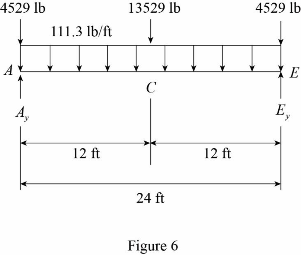
Refer Figure 6.
The reaction at A and E are denoted by
The dead load on the beam is symmetrical. Then,
Show the loading on the girder AE as shown in Figure 7.
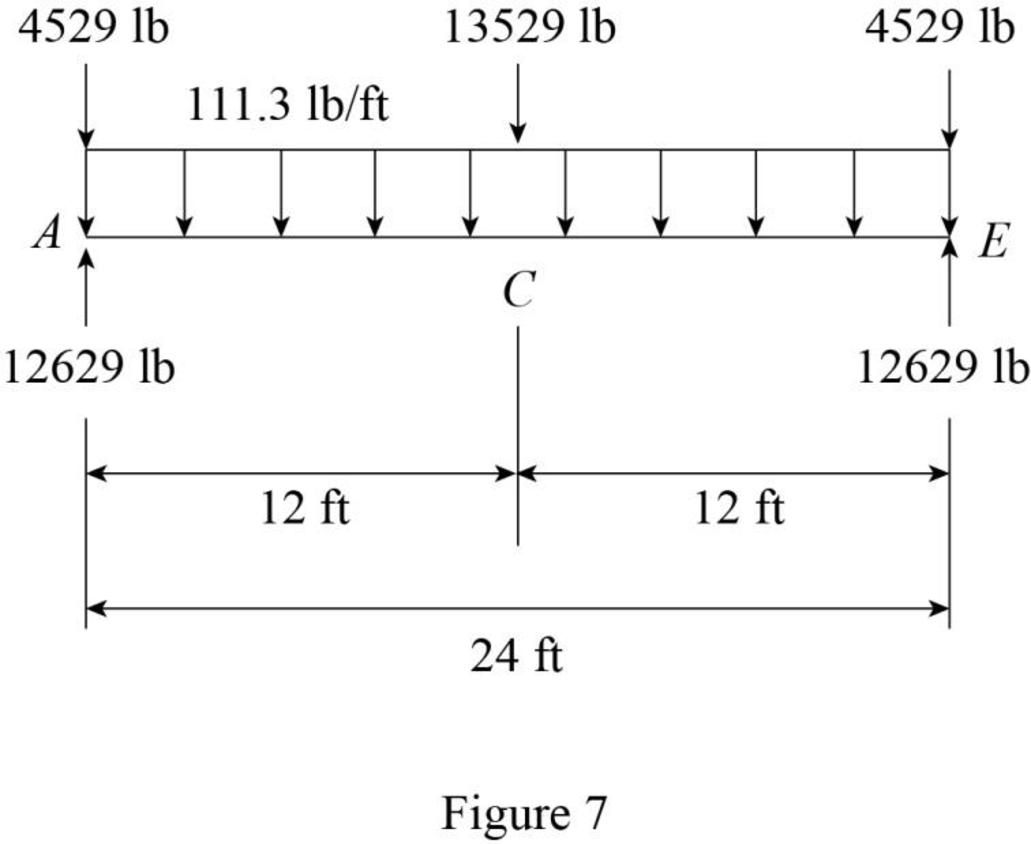
Refer Figure 7.
The dead load at C, A, and E are
The uniformly distributed load in the girder AE is
Want to see more full solutions like this?
Chapter 2 Solutions
Structural Analysis, Si Edition


- The floor of an apartment building, shown in the figure, is subjected to a uniformly distributed load of 45 psf over its surface area. The aspect ratio (beam length to spacing ratio) of the slabs in the framing plan is 40 ft/25 ft = 1.6. The load path is: concrete slabs - floor beams - girders - columns - foundations. 1. Determine the loads acting on the floor beams AF, BG, and CH of the framing system. Sketch the tributary area of the beams selected on the building framing plan. Draw the free body diagram of the beams selected.arrow_forwardi support settlements should be considered in design- erminate structures. The structure must be designed ost unfavorable combination of loads. Problems 49 Section 2.2 2.5 The floor system of an apartment building consists of a 4-in.-thick reinforced concrete slab resting on three steel floor beams, which in turn are supported by two steel girders, as shown in Fig. P2.5. The areas of cross section of the floor beams and the girders are 18.3 in.² and 32.7 in.², respectively. Determine the dead loads acting on the beam CD and the girder AE. 2.6 Solve Problem 2.5 if a 6-in.-thick brick wall, which is 7 ft high and 25 ft long, bears directly on the top of beam CD. See Fig. P2.5. AF 25 ft Steel girder (A = 32.7 in.²) Steel column 4 in. concrete slab 2 at 12 ft = 24 ft Steel floor beam (A = 18.3 in.2) I F FIG. P2.5, P2.6, P2.9 27 The floor svetom of o qymnosium consists of o 130arrow_forwardQ. No 7: The cross section of the beam has a uniform wall thickness. Analyze using concepts of shear stress, shear flow and shear centre in thin walled open section beams to determine the location of the shear center relative to point B. 6 in. -6 in. 3 in. 0.1 in. 3 in. NA B. 3 in. 3 in.arrow_forward
- 3. The steel framing plan of a small building is shown in Figure 1.3a. The floor consists of a 5-in.-thick reinforced concrete slab supported on steel beams (see section 1-1 in Figure 1.3b). Beams are connected to each other and to the corner columns by clip angles; see Figure 1.3c. The clip angles are assumed to provide the equivalent of a pin support for the beams; that is, they can transmit vertical load but no moment. An acoustical board ceiling, which weighs 1.5 lb/ft?, is suspended from the concrete slab by closely spaced supports, and it can be treated as an additional uniform load on the slab. To account for the weight of ducts, piping, conduit, and so forth, located between the slab and ceiling (and supported by hangers from the slab), an additional dead load allowance of 20 lb/ft? is assumed. The designer initially estimates the weight of beams B1 at 30 lbft and the 24-ft girders B2 on column lines 1 and 2 at 50 lb/ft. Establish the magnitude of the dead load distribution on…arrow_forwardThe steel reinforced concrete slab shown in Fig. Q3 below has a 200mm thickness and is supported by 3 concrete beam girders at equal spacing of 9m. The deck is monolithically attached to the girders and has a total length of 20m and a width of 10m. It is reinforced with 15 x q16 steel bars across the length (19m length each bar) and 10 x p16 steel bars across the width (9m each bar). 3. 9 m Fig. Q3 (a) Assuming a nominal concrete unit weight of 25kN/m' and a steel unit weight of 78kN/m³, calculate the dead load G in kN. Consider only the deck selfweight and the selfweight of the steel reinforcement. Neglect the concrete beam girders. (b) The concrete deck carries a live load Q of 6kN/m Determine the total design load of the deck for the ultimate (ULS) and serviceability limit states (SLS) in kN (neglect the beam girders). (c) A steel column is 4m long and has a diameter of 0.50m. It is subjected to a compressive force of 20MN. Given that the, elastic modulus of the material is 210GPA,…arrow_forwardA structural framing plan for the upper floors in a building is shown in the figure below. A site-cast concrete slab-and-beam system is used. The floor framing system consists of a series of parallel beams at 2.8-meter centers that support a continuous one-way spanning slab (adjacent columns are spaced by a distance of 8.4-meter in both horizontal and vertical directions). The uniformly ultimate (factored) distributed load for the one-way slab is equal to 14 kN/m2. Ignore the own weights of beams and walls. Compute the value of load on column H. Compute the value of distributed load on beam EF. Compute the value of each of concentrated loads on beam HK. Compute the value of maximum moment for beam HK.arrow_forward
- A floor opening in a building is to be closed by pouring a concrete slab. The proposed framing is composed ofwood joist assumed to be simply supported and given with a total load of 4 kPa. What is the maximum flexural stress in 40 mm x 190 mm wood joist if its span is 3 m and spaced atevery 0.30 m on centers?a. 5.61 MPa c. 6.78 MPab. 7.23 MPa d. 4.65 MPa What is the maximum shearing stress in the said joists?a. 0.40 MPa c. 0.36 MPab. 0.69 MPa d. 0.54 MPaarrow_forward6.64 Two beams carrying identical loads, simply supported, are having same depth but beam A has double the width as compared to that of beam B. The ratio of the strength of beam A to that of heam B isarrow_forwardGiven. A two-story OCBF shown in Fig. 3.40c that forms part of the building frame system in SDC E. The axial loads on the ground floor brace B1 are as follows: Dead load D= 30 kips Live load L= 15 kips Seismic force QE = ±80 kips Snow load S= 0 kips Hydrostatic load H = 0 The redundancy coefficient p = 1.1. Mapped two-second såpectral acceleration, Sps = 0.826 g. Required. Determine a pipe section for brace B1, ASTM A53 Grade B steel; F, = 35 ksi, F = 60 ksi 16 ft 16 ft Figure -15 ft B2 B1 -- -15 ft B2 B1 Ordinary concentric brace frame (OCBF) example.arrow_forward
- a- Calculate the ultimate shear force at point A of the continuous beam shown in Fig.3? 10% b-Calculate the number of bars of the compression reinforcement (As') in the doubly reinforced shown in Fig.2. Assume: Mu=480 kN.m, M2 = 300 kN.m, fy =400 N/mm², fe'- 25 N/mm², bar diameter 25 mm. 25% 03 (35%) S d-500 As. b-300 Id=64 As'arrow_forwardProblem 2. Determine the minimum height h of the beam shown in the figure if the flexural stress is not to exceed 20 Mpa. 1m 2.6 kN/m R₁ 6 KN 3 m 2 m R₂ 80 mm harrow_forwardGiven is the 200mm X 400 mm rectangular beam below. 9 kN 7.50 kN/m 400 mm 1.50 kNm A C 200 mm 1.50m 7.50m R2 R1 Figure 1 What is the value of the maximum flerural in MPa?arrow_forward

 Structural Analysis (10th Edition)Civil EngineeringISBN:9780134610672Author:Russell C. HibbelerPublisher:PEARSON
 Principles of Foundation Engineering (MindTap Cou...Civil EngineeringISBN:9781337705028Author:Braja M. Das, Nagaratnam SivakuganPublisher:Cengage Learning
 Fundamentals of Structural AnalysisCivil EngineeringISBN:9780073398006Author:Kenneth M. Leet Emeritus, Chia-Ming Uang, Joel LanningPublisher:McGraw-Hill Education
 Traffic and Highway EngineeringCivil EngineeringISBN:9781305156241Author:Garber, Nicholas J.Publisher:Cengage Learning