
Introductory Circuit Analysis
13th Edition
ISBN: 9780133923919
Author: Boylestad, Robert L.
Publisher: Pearson Education
expand_more
expand_more
format_list_bulleted
Videos
Textbook Question
Chapter 20, Problem 17P
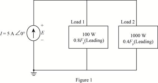
For the circuit of Fig. 20.62:
- Find the total number of watts, volt-amperes reactive, volt-amperes, and Fp.
- Find the voltage E.
- Find the type of elements and their impedance in each box. (Assume that the elements within each box are in series.)
Expert Solution & Answer
Want to see the full answer?
Check out a sample textbook solution
Students have asked these similar questions
For the network of Fig. 20.56:
a. Find Is.
b. Find the average power delivered to each element.
c. Find the reactive power for each element.
d. Find the apparent power for each element.
e. Find PT, QT, ST, and Fp for the system.
f. Sketch the power triangle.
Please answer all subpart either 100% dislike is ready please all subpart in short and clear handwriting or typing
also given IL=50mA
For balanced condition, find Q in Maxwell bridge if R1=250Ω, C1=4µF, R2=50Ω, R3=20Ω, f=60Hz .
Chapter 20 Solutions
Introductory Circuit Analysis
Ch. 20 - For the battery of bulbs (purely resistive)...Ch. 20 - For the network of Fig. 20.49 : a. Find the...Ch. 20 - For the network of Fig. 20.50 : a. Determine the...Ch. 20 - For the system of Fig. 20.51 : a. Find the total...Ch. 20 - For the system of Fig. 20.52 : a. Find PT, QT. and...Ch. 20 - 6. For the system of Fig. 20.53 : a. Find PT, QT....Ch. 20 - For the network of Fig. 20.54 : a. Find the type...Ch. 20 - For the circuit of Fig. 20.55: a. Find the...Ch. 20 - For the network of Fig. 20.56 : a. Find Is. b....Ch. 20 - Repeat Problem 9 for the network of Fig. 20.57.
Ch. 20 - For the network of Fig. 20.58: a. Find the average...Ch. 20 - An electrical system is rated 10 kVA, 200 V at a...Ch. 20 - An electrical system is rated 5 kVA, 120 V, at a...Ch. 20 - For the system of Fig. 20.59: a. Find the total...Ch. 20 - Repeat Problem 14 for the system of Fig. 20.60.Ch. 20 - For the circuit of Fig. 20.61: Find the total...Ch. 20 - For the circuit of Fig. 20.62: Find the total...Ch. 20 - Prob. 18PCh. 20 - The load on a 120 V, 60 Hz supply is 5 kW...Ch. 20 - The loading of a factory on a 1000 V, 60 Hz system...Ch. 20 - a. A wattmeter is connected with its current coil...Ch. 20 - The voltage source in Fig. 20.64 delivers 660 VA...Ch. 20 - a. An air-core coil is connected to a 200 V, 60 Hz...Ch. 20 - a. The inductance of an air-core coil is 0.08 H....Ch. 20 - Using PSpice or Multisim, obtain a plot of...
Knowledge Booster


Learn more about
Need a deep-dive on the concept behind this application? Look no further. Learn more about this topic, electrical-engineering and related others by exploring similar questions and additional content below.Similar questions
- Company Y would like to have a new installation transmission line to open a small new city consist of 300 MW with 0.85 power factor lagging at full load. The new transmission line required 132 kV with 124.274 miles long. All the elements needed for the new transmission line is listed in table shown in the picture. You are required to model the transmission line and analysed the performance of the new transmission lines in terms of voltage regulation and efficiency. Note that the frequency used is 50 Hz.arrow_forwardFor the circuit shown,a) To the coil of a henry, measure its internal resistance and the value of the inductance.b) Measure the effective voltage and current at the terminals of the 100 Ω resistor and at the source.c) Measure the average power delivered by the source.Note the phase shift between the supply voltage and the voltage across the 100 Ω resistor (only at this point).arrow_forwardIbc find the load current Vca find the line voltage Calculate the complex power on the transmission linearrow_forward
- a plant is feeding a load 1.2k feet away. the load demands 100 amps at 500V. an ac system with transformer rated 500/5000V near the generating station and 5000/500V near the load. if the line has resistance of 0.2 ohms and receiving voltage of 500V, find the sending end voltage and powerflows and transmission losses.arrow_forwarddetermine Vo, if Vs = 8 cos 1000t V.arrow_forwardIn the circuit shown below, find Z for w=1000 rad/sec.arrow_forward
- . At a 12.47 kV (line to line) distribution system the communication interference (CI) was observed due to 5% of 5th harmonic currents generated by a 3000 kVA arc furnace. In order to avoid CI it is required to convert an existing 600 kVAr capacitor to 5th harmonic filter considering the total kVAr should not exceed 135%. Calculate the following: (i) Capacitor reactance (ii) Reactance of the series reactor (iii) Fundamental frequency current (iv) 5th harmonic frequency current (v) Tuned frequency voltage (vi) Total rms current (vii) Fundamental frequency voltage (viii) Voltage (rms) across the capacitor bank (ix) Check whether the filter kVAr rating is within limit? (x) Comment how the existing capacitor bank is converted to filterarrow_forwardIdentify the company or private distributor of electricity involved in primary power distribution in the PHILIPPINES. (Example: NGCP)arrow_forwardYou are given a transmission line with a characteristic impedance Zo of 40 + j60 ohms. The line is connected to a generator with a voltage of Vg = 20∠30° V and an internal impedance Zg of 0 ohms. The line is matched to the load with an impedance ZL of 40 + j60 ohms. You are asked to calculate the input voltage Vin and the input current Iin in the transmission line.arrow_forward
arrow_back_ios
SEE MORE QUESTIONS
arrow_forward_ios
Recommended textbooks for you
 Introductory Circuit Analysis (13th Edition)Electrical EngineeringISBN:9780133923605Author:Robert L. BoylestadPublisher:PEARSON
 Delmar's Standard Textbook Of ElectricityElectrical EngineeringISBN:9781337900348Author:Stephen L. HermanPublisher:Cengage Learning
 Programmable Logic ControllersElectrical EngineeringISBN:9780073373843Author:Frank D. PetruzellaPublisher:McGraw-Hill Education
 Fundamentals of Electric CircuitsElectrical EngineeringISBN:9780078028229Author:Charles K Alexander, Matthew SadikuPublisher:McGraw-Hill Education
 Electric Circuits. (11th Edition)Electrical EngineeringISBN:9780134746968Author:James W. Nilsson, Susan RiedelPublisher:PEARSON
 Engineering ElectromagneticsElectrical EngineeringISBN:9780078028151Author:Hayt, William H. (william Hart), Jr, BUCK, John A.Publisher:Mcgraw-hill Education,
Introductory Circuit Analysis (13th Edition)
Electrical Engineering
ISBN:9780133923605
Author:Robert L. Boylestad
Publisher:PEARSON
Delmar's Standard Textbook Of Electricity
Electrical Engineering
ISBN:9781337900348
Author:Stephen L. Herman
Publisher:Cengage Learning
Programmable Logic Controllers
Electrical Engineering
ISBN:9780073373843
Author:Frank D. Petruzella
Publisher:McGraw-Hill Education
Fundamentals of Electric Circuits
Electrical Engineering
ISBN:9780078028229
Author:Charles K Alexander, Matthew Sadiku
Publisher:McGraw-Hill Education
Electric Circuits. (11th Edition)
Electrical Engineering
ISBN:9780134746968
Author:James W. Nilsson, Susan Riedel
Publisher:PEARSON
Engineering Electromagnetics
Electrical Engineering
ISBN:9780078028151
Author:Hayt, William H. (william Hart), Jr, BUCK, John A.
Publisher:Mcgraw-hill Education,
02 - Sinusoidal AC Voltage Sources in Circuits, Part 1; Author: Math and Science;https://www.youtube.com/watch?v=8zMiIHVMfaw;License: Standard Youtube License