
Introductory Circuit Analysis
13th Edition
ISBN: 9780133923919
Author: Boylestad, Robert L.
Publisher: Pearson Education
expand_more
expand_more
format_list_bulleted
Videos
Textbook Question
Chapter 20, Problem 22P
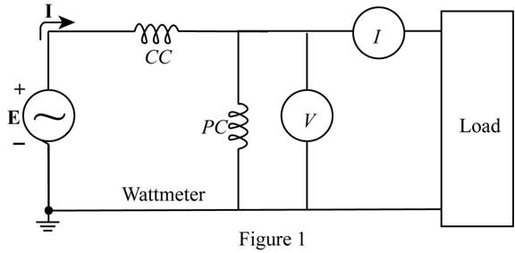
The voltage source in Fig. 20.64 delivers 660 VA at 120 V, with a supply current that lags the voltage by a power factor of 0.6.
a. Determine the voltmeter, ammeter, and wattmeter readings.
b. Find the load impedance in rectangular form.
Expert Solution & Answer
Want to see the full answer?
Check out a sample textbook solution
Students have asked these similar questions
Discussion1. Determine the impedance of an ideal open stub with an electrical length of 35oat 2.4 GHz.
For the circuit shown,a) To the coil of a henry, measure its internal resistance and the value of the inductance.b) Measure the effective voltage and current at the terminals of the 100 Ω resistor and at the source.c) Measure the average power delivered by the source.Note the phase shift between the supply voltage and the voltage across the 100 Ω resistor (only at this point).
A 550-V feeder line supplies an industrial plant consisting of a motor drawing 60 kW at 0.75
pf (inductive), a capacitor with a rating of 20 kVAR, and lighting drawing 10 kW.
(a) Calculate the total reactive power and apparent power absorbed by the plant.
(b) Determine the overall pf.
(c) Find the current in the feeder line.
Chapter 20 Solutions
Introductory Circuit Analysis
Ch. 20 - For the battery of bulbs (purely resistive)...Ch. 20 - For the network of Fig. 20.49 : a. Find the...Ch. 20 - For the network of Fig. 20.50 : a. Determine the...Ch. 20 - For the system of Fig. 20.51 : a. Find the total...Ch. 20 - For the system of Fig. 20.52 : a. Find PT, QT. and...Ch. 20 - 6. For the system of Fig. 20.53 : a. Find PT, QT....Ch. 20 - For the network of Fig. 20.54 : a. Find the type...Ch. 20 - For the circuit of Fig. 20.55: a. Find the...Ch. 20 - For the network of Fig. 20.56 : a. Find Is. b....Ch. 20 - Repeat Problem 9 for the network of Fig. 20.57.
Ch. 20 - For the network of Fig. 20.58: a. Find the average...Ch. 20 - An electrical system is rated 10 kVA, 200 V at a...Ch. 20 - An electrical system is rated 5 kVA, 120 V, at a...Ch. 20 - For the system of Fig. 20.59: a. Find the total...Ch. 20 - Repeat Problem 14 for the system of Fig. 20.60.Ch. 20 - For the circuit of Fig. 20.61: Find the total...Ch. 20 - For the circuit of Fig. 20.62: Find the total...Ch. 20 - Prob. 18PCh. 20 - The load on a 120 V, 60 Hz supply is 5 kW...Ch. 20 - The loading of a factory on a 1000 V, 60 Hz system...Ch. 20 - a. A wattmeter is connected with its current coil...Ch. 20 - The voltage source in Fig. 20.64 delivers 660 VA...Ch. 20 - a. An air-core coil is connected to a 200 V, 60 Hz...Ch. 20 - a. The inductance of an air-core coil is 0.08 H....Ch. 20 - Using PSpice or Multisim, obtain a plot of...
Additional Engineering Textbook Solutions
Find more solutions based on key concepts
Identify the type of input and output configuration for each diff-amp in Figure 18-35.
Electronics Fundamentals: Circuits, Devices & Applications
Does the severity of an electric shock increase ordecrease with eh of the following changes? a. A decrease in t...
Electric Motors and Control Systems
What is the color code for a 365- five-band precision resistor with a tolerance of 5 percent?
ELECTRICITY FOR TRADES (LOOSELEAF)
Explain the main function of each of the following major components of a PLC: a. Processor module (CPU) b. I/O ...
Programmable Logic Controllers
With respect to the circuit in Fig. 5.90, (a) employ Thévenin’s theorem to determine the equivalent network see...
Loose Leaf for Engineering Circuit Analysis Format: Loose-leaf
Find I0 and I1 in the circuit in Fig.P2.12.
Basic Engineering Circuit Analysis
Knowledge Booster


Learn more about
Need a deep-dive on the concept behind this application? Look no further. Learn more about this topic, electrical-engineering and related others by exploring similar questions and additional content below.Similar questions
- Compute the power factor and the reactive factorfor the network inside the box in Fig. 10.6,whose voltage and current are described inExample 10.1.Hint: Use -i to calculate the power and reactivefactorsarrow_forwarddetermine Vo, if Vs = 8 cos 1000t V.arrow_forwardObtain an expression for the power dissipated in the 10 resistor of Fig10.49arrow_forward
- Company Y would like to have a new installation transmission line to open a small new city consist of 300 MW with 0.85 power factor lagging at full load. The new transmission line required 132 kV with 124.274 miles long. All the elements needed for the new transmission line is listed in table shown in the picture. You are required to model the transmission line and analysed the performance of the new transmission lines in terms of voltage regulation and efficiency. Note that the frequency used is 50 Hz.arrow_forward. A 46KV 0.8 lagging power factor load is connected to the end of a short transmission line wherethe voltage is 230. If the line resistance and reactance are 0.06 and 0.08 ohm, respectively,calculate the voltage at the sending end.arrow_forwardIn the circuit shown below, find Z for w=1000 rad/sec.arrow_forward
- A transmission line of impedance (0.05 + j0.02) pu interconnects the buses of a switchyard and a bulk supply point. The receiving end apparent power is (1.0 + j0.6) pu and sending end voltage, 1/0°pu. Estimate the following: i) Receiving end voltage after two iterations ii) Perform two further iterations to test the convergence of the value of receiving end voltage deduced in (i) iii) load currentarrow_forwardYou are given a transmission line with a characteristic impedance Zo of 40 + j60 ohms. The line is connected to a generator with a voltage of Vg = 20∠30° V and an internal impedance Zg of 0 ohms. The line is matched to the load with an impedance ZL of 40 + j60 ohms. You are asked to calculate the input voltage Vin and the input current Iin in the transmission line.arrow_forwardPRACTICE 10.11 Determine the admittance (in rectangular form) of (a) an impedance Z 1000+ j400 2: (b) a network consisting of the parallel combination of an 800 52 resistor, a 1 mH inductor, and a 2 nF capacitor, if = 1 Mrad/s; (c) a network consisting of the series com- bination of an 800 2 resistor, a 1 mH inductor, and a 2 nF capacitor, if ∞ = 1 Mrad/s. Ans: 0.862-j0.345 mS: 1.25 + j1 mS: 0.899- j0.562 ms.arrow_forward
- Identify the company or private distributor of electricity involved in primary power distribution in the PHILIPPINES. (Example: NGCP)arrow_forwardFind the line and phase voltage if Vcn= 30<50 V. Assuming ACB sequencearrow_forwardGiven the circuit below with input v(t) = 28.28(40kpit) a. find the MAGNITUDE of the total impedance (in ohms with 2 decimal places)arrow_forward
arrow_back_ios
SEE MORE QUESTIONS
arrow_forward_ios
Recommended textbooks for you
 Introductory Circuit Analysis (13th Edition)Electrical EngineeringISBN:9780133923605Author:Robert L. BoylestadPublisher:PEARSON
 Delmar's Standard Textbook Of ElectricityElectrical EngineeringISBN:9781337900348Author:Stephen L. HermanPublisher:Cengage Learning
 Programmable Logic ControllersElectrical EngineeringISBN:9780073373843Author:Frank D. PetruzellaPublisher:McGraw-Hill Education
 Fundamentals of Electric CircuitsElectrical EngineeringISBN:9780078028229Author:Charles K Alexander, Matthew SadikuPublisher:McGraw-Hill Education
 Electric Circuits. (11th Edition)Electrical EngineeringISBN:9780134746968Author:James W. Nilsson, Susan RiedelPublisher:PEARSON
 Engineering ElectromagneticsElectrical EngineeringISBN:9780078028151Author:Hayt, William H. (william Hart), Jr, BUCK, John A.Publisher:Mcgraw-hill Education,
Introductory Circuit Analysis (13th Edition)
Electrical Engineering
ISBN:9780133923605
Author:Robert L. Boylestad
Publisher:PEARSON
Delmar's Standard Textbook Of Electricity
Electrical Engineering
ISBN:9781337900348
Author:Stephen L. Herman
Publisher:Cengage Learning
Programmable Logic Controllers
Electrical Engineering
ISBN:9780073373843
Author:Frank D. Petruzella
Publisher:McGraw-Hill Education
Fundamentals of Electric Circuits
Electrical Engineering
ISBN:9780078028229
Author:Charles K Alexander, Matthew Sadiku
Publisher:McGraw-Hill Education
Electric Circuits. (11th Edition)
Electrical Engineering
ISBN:9780134746968
Author:James W. Nilsson, Susan Riedel
Publisher:PEARSON
Engineering Electromagnetics
Electrical Engineering
ISBN:9780078028151
Author:Hayt, William H. (william Hart), Jr, BUCK, John A.
Publisher:Mcgraw-hill Education,
Inductors Explained - The basics how inductors work working principle; Author: The Engineering Mindset;https://www.youtube.com/watch?v=KSylo01n5FY;License: Standard Youtube License