
Electric Motor Control
10th Edition
ISBN: 9781133702818
Author: Herman
Publisher: CENGAGE L
expand_more
expand_more
format_list_bulleted
Concept explainers
Videos
Textbook Question
Chapter 21, Problem 10SQ
In place of the push buttons in Figure 21–4, draw a heavy-duty selector switch for forward-reverse-stop control. Show the target table for this selector switch.
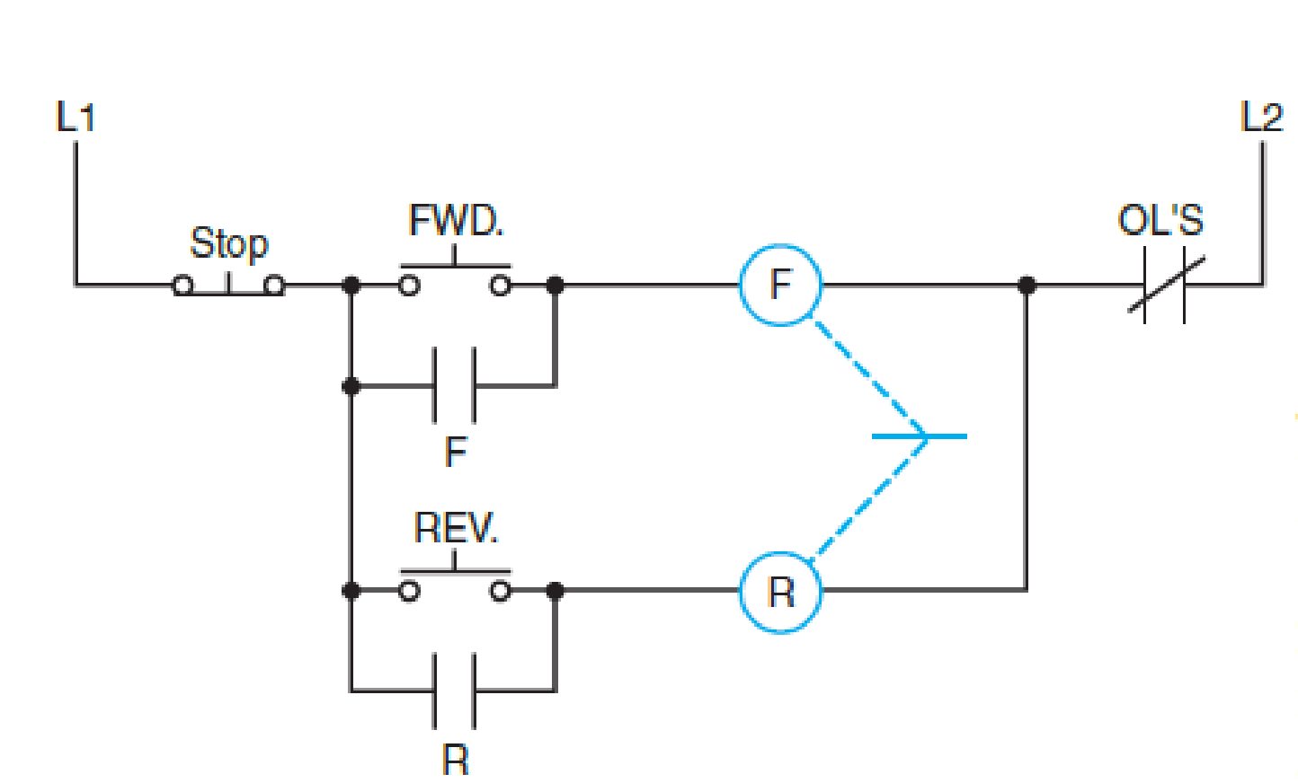
FIG. 21–4
Expert Solution & Answer

Trending nowThis is a popular solution!

Students have asked these similar questions
Q.35
When overload contacts are connected into a control circuit, are they connected in series with the starter coil or in parallel with the starter coil?
Select one:
A. PARALLEL
B. SERIES
Draw an schematic control diagram of a reversing starter. Use a standard-duty selector switch with forward, reverse, and stop push buttons with three methods of interlocking.
5-Draw the diagram of a control valve showing all the parts. Explain the pneumatic actuator in detail
Chapter 21 Solutions
Electric Motor Control
Ch. 21 - How is a change in the direction of rotation of a...Ch. 21 - Prob. 2SQCh. 21 - If a reversing control circuit contains...Ch. 21 - How is auxiliary contact interlocking achieved on...Ch. 21 - After the forward coil has been energized, is the...Ch. 21 - If a mechanical interlock is the only means of...Ch. 21 - If pilot lights are to indicate which coil is...Ch. 21 - What is the sequence of the operations if the...Ch. 21 - In place of the push buttons in Figure 214, draw a...Ch. 21 - From the elementary drawing in Figure 2110,...
Knowledge Booster


Learn more about
Need a deep-dive on the concept behind this application? Look no further. Learn more about this topic, electrical-engineering and related others by exploring similar questions and additional content below.Similar questions
- Which of the following applies to an autotransformer starter with a five-pole starting contactor: open transition or closed transition? Locate in Figure 273.arrow_forwardRefer to the basic control schematic in Figure 344. The limit switch is shown as a. normally open. b. normally closed. c. normally open held closed. d. normally closed held open. Fig. 344 Wiring diagram of manual speed regulator interlocked with magnetic starter for control of slip ring motor (three-wire control).arrow_forwardWhat is the difference between a manual faceplate starter and a manual faceplate regulator?arrow_forward
- Convert the control circuit only, Figure 2111, from the wiring diagram to an elementary diagram. Include the limit switches (RLS, FLS) as operating in the control circuit.arrow_forwardDraw an electrical diagram for a Star Delta starter with a forward rotation and reverse rotation switch.arrow_forwardQ.11 A normally open auxiliary contact connected in parallel to maintain a circuit to the relay coil when the push button is released is part of what type of control circuit? Select one: A. START-STOP PUSH BUTTON B. JOGGING SWITCH C. STARTING SWITCH D. EMERGENCY STOP BUTTONarrow_forward
- Select the best answer for each of the following. When the reset button does not reestablish the control circuit after an overload, the probable cause is a. the overload heater is too small. b. the overload trip has not cooled sufficiently. c. the auxiliary contacts are defective. d. the overload heater is burned out.arrow_forwardAfter the forward coil has been energized, is the auxiliary forward interlocking contact open or closed?arrow_forward2. In the motor control circuit of Figure 11 in your study unit, the operation of any one of the overload relays has which of the following effects?A. The motor only runs two phases.B. The motor operates normally. C. The auxiliary contact M closes. D. The motor stopsarrow_forward
- Compare a thick-wired thermocouple versus a thin-wired thermocouple. Which will respond more quickly to small temperature changes? Why?arrow_forwardA starter turns very slowly and has excessive cranking current draw. When removed from the vehicle and bench tested, the starter spins normally and current draw is within specifications. Technician A says poor battery connections may be the cause. Technician B says an internal engine problem may be the cause. Who is correct?arrow_forward
arrow_back_ios
arrow_forward_ios
Recommended textbooks for you

 Electricity for Refrigeration, Heating, and Air C...Mechanical EngineeringISBN:9781337399128Author:Russell E. SmithPublisher:Cengage Learning
Electricity for Refrigeration, Heating, and Air C...
Mechanical Engineering
ISBN:9781337399128
Author:Russell E. Smith
Publisher:Cengage Learning
Single Phase Induction Motor, How it works ?; Author: Lesics;https://www.youtube.com/watch?v=awrUxv7B-a8;License: Standard Youtube License