
COLL PHYSICS UPDATE V2&S/WRKBK&MOD MST/
3rd Edition
ISBN: 9780134677149
Author: Knight
Publisher: PEARSON
expand_more
expand_more
format_list_bulleted
Videos
Textbook Question
Chapter 21, Problem 33P
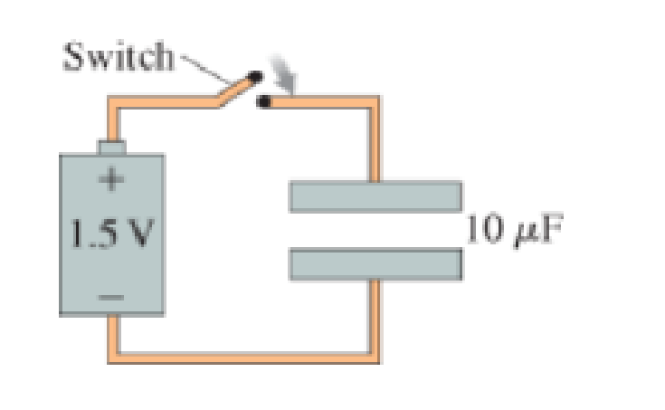
Initially, the switch in Figure P21 .33 is open and the capacitor is uncharged. How much charge flows through the switch after the switch is closed?
Figure P21.33
Expert Solution & Answer
Want to see the full answer?
Check out a sample textbook solution
Chapter 21 Solutions
COLL PHYSICS UPDATE V2&S/WRKBK&MOD MST/
Ch. 21 - By moving a 10 nC charge from point A to point B,...Ch. 21 - Charge q is fired through a small hole in the...Ch. 21 - Why is the potential energy of two opposite...Ch. 21 - An electron (q = e) completes half of a circular...Ch. 21 - An electron moves along the trajectory from i to f...Ch. 21 - The graph in Figure Q21.61Q shows the electric...Ch. 21 - As shown in Figure Q21.7, two protons are launched...Ch. 21 - Each part of Figure Q21.8 shows one or more point...Ch. 21 - Figure Q21.9 shows two points inside a capacitor....Ch. 21 - A capacitor with plates separated by distanced is...
Ch. 21 - Rank in order, from most positive to most...Ch. 21 - Figure Q21.12 shows two points near a positive...Ch. 21 - A. Suppose that E = 0, throughout some region of...Ch. 21 - Rank in order, from largest to smallest, the...Ch. 21 - Figure Q21.16 shows an electric field diagram....Ch. 21 - Figure Q21.17 shows a negatively charged...Ch. 21 - Rank in order, from largest to smallest, the...Ch. 21 - A parallel-plate capacitor with plate separation d...Ch. 21 - A proton is launched from point 1 in Figure Q21...Ch. 21 - A 1.0 nC positive point charge is located at point...Ch. 21 - A 100 V battery is connected across the plates of...Ch. 21 - The electric potential is 300 V at x = 0 cm, is...Ch. 21 - What is the potential at point c? A. 400 v B. 350...Ch. 21 - At which point, a, b, or c, is the magnitude of...Ch. 21 - What is the approximate magnitude of the electric...Ch. 21 - The direction of the electric field at point b is...Ch. 21 - A +10 nC charge is moved from point c to point a....Ch. 21 - A bug zapper consists of two metal plates...Ch. 21 - An atom of helium and one of argon are singly...Ch. 21 - The dipole moment of the heart is shown at a...Ch. 21 - Moving a charge from point A, where the potential...Ch. 21 - The graph in Figure P21.2 shows the electric...Ch. 21 - It takes 3.0 J of work to move a 15 nC charge from...Ch. 21 - A 20 nC charge is moved from a point where V = 150...Ch. 21 - At one point in space, the electric potential...Ch. 21 - An electron has been accelerated from rest through...Ch. 21 - A proton has been accelerated from rest through a...Ch. 21 - What potential difference is needed to accelerate...Ch. 21 - An electron with an initial speed of 500,000 m/s...Ch. 21 - A proton with an initial speed of 800,000 m/s is...Ch. 21 - The electric potential at a point that is halfway...Ch. 21 - A 2.0 cm 2.0 cm parallel-plate capacitor has a...Ch. 21 - Two 2.00 cm 2.00 cm plates that form a...Ch. 21 - A. In Figure P21.14, which capacitor plate, left...Ch. 21 - A +25 nC charge is at the origin. How much farther...Ch. 21 - A. What is the electric potential at points A, B,...Ch. 21 - A 1.0-cm-diameter sphere is charged to a potential...Ch. 21 - What is the electric potential at the point...Ch. 21 - a. What is the potential difference between the...Ch. 21 - A. In Figure P21.20, which point, A or B, has a...Ch. 21 - In Figure P21.21, the electric potential at point...Ch. 21 - What is the potential difference between xi = 10...Ch. 21 - What are the magnitude and direction of the...Ch. 21 - What are the magnitude and direction of the...Ch. 21 - Two 2.0 cm 2.0 cm square aluminum electrodes,...Ch. 21 - An uncharged capacitor is connected to the...Ch. 21 - You need to construct a 100 pF capacitor for a...Ch. 21 - A switch that connects a battery to a 10 F...Ch. 21 - What is the voltage of a battery that will charge...Ch. 21 - Two electrodes connected to a 9.0 V battery are...Ch. 21 - Initially, the switch in Figure P21 .33 is open...Ch. 21 - A 1.2 nF parallel-plate capacitor has an air gap...Ch. 21 - A science-fair radio uses a homemade capacitor...Ch. 21 - A 25 pF parallel-plate capacitor with an air gap...Ch. 21 - Two 2.0-cm-diameter electrodes with a 0.1...Ch. 21 - A parallel-plate capacitor is connected to a...Ch. 21 - A parallel-plate capacitor is charged by a 12.0 V...Ch. 21 - To what potential should you charge a 1.0 F...Ch. 21 - A pair of 10 F capacitors in a high-power laser...Ch. 21 - Capacitor 2 has half the capacitance and twice the...Ch. 21 - Two uncharged metal spheres, spaced 15.0 cm apart,...Ch. 21 - 50 pJ of energy is stored in a 2.0 cm 2.0 cm 2.0...Ch. 21 - A 2.0-cm-diameter parallel-plate capacitor with a...Ch. 21 - What is the change in electric potential energy of...Ch. 21 - What is the potential difference V34 in Figure...Ch. 21 - A 50 nC charged particle is in a uniform electric...Ch. 21 - At a distance r from a point charge, the electric...Ch. 21 - The 4000 V equipotential surface is 10.0 cm...Ch. 21 - What is the electric potential energy of the...Ch. 21 - Two point charges 2.0 cm apart have an electric...Ch. 21 - Two positive point charges are 5.0 cm apart. If...Ch. 21 - A +3.0 nC charge is at x = 0 cm and a 1.0 nC...Ch. 21 - A 3.0 nC charge is on the x-axis at x = 9 cm and a...Ch. 21 - A 10.0 nC point charge and a +20.0 nC point charge...Ch. 21 - A 2.0-mm-diameter glass bead is positively...Ch. 21 - In a semiclassical model of the hydrogen atom, the...Ch. 21 - What is the electric potential at the point...Ch. 21 - a. What is the electric potential at point A in...Ch. 21 - A protons speed as it passes point A is 50,000...Ch. 21 - A proton follows the path shown in Figure P21.63....Ch. 21 - Electric outlets have a voltage of approximately...Ch. 21 - Estimate the magnitude of the electric field in a...Ch. 21 - A Na+ion moves from inside a cell, where the...Ch. 21 - Suppose that a molecular ion with charge 10e is...Ch. 21 - The electric field strength is 50,000 V/m inside a...Ch. 21 - A parallel-plate capacitor is charged to 5000 V. A...Ch. 21 - A proton is released from rest at the positive...Ch. 21 - The electric field strength is 20,000 V/m inside a...Ch. 21 - In the early 1900s, Robert Millikan used small...Ch. 21 - Two 2.0-cm-diameter disks spaced 2.0 mm apart form...Ch. 21 - In proton-beam therapy, a high-energy beam of...Ch. 21 - A 2.5-mm-diameter sphere is charged to 4.5 nC. An...Ch. 21 - A proton is fired from far away toward the nucleus...Ch. 21 - Two 10.0-cm-diameter electrodes 0.50 cm apart form...Ch. 21 - Two 10.0-cm-diameter electrodes 0.50 cm apart form...Ch. 21 - Determine the magnitude and direction of the...Ch. 21 - Figure P21.81 shows the electric potential on a...Ch. 21 - A capacitor consists of two 6.0-cm-diameter...Ch. 21 - The dielectric in a capacitor serves two purposes....Ch. 21 - The highest magnetic fields in the world are...Ch. 21 - The flash unit in a camera uses a special circuit...Ch. 21 - A Lightning Strike Storm clouds build up large...Ch. 21 - A Lightning Strike Storm clouds build up large...Ch. 21 - A Lightning Strike Storm clouds build up large...Ch. 21 - A Lightning Strike Storm clouds build up large...Ch. 21 - A Lightning Strike Storm clouds build up large...
Additional Science Textbook Solutions
Find more solutions based on key concepts
When the momentum of an object or system of objects does not change with time, the momentum of the object or sy...
Tutorials in Introductory Physics
* How can the pressure of air in your house stay constant during the day if the temperature rises? Estimate the...
College Physics
Whats the longest wavelength of light you could use to resolve a structure with angular diameter 0.44 mrad, usi...
Essential University Physics: Volume 2 (3rd Edition)
If acceleration is proportional to the net force or is equal to net force.
Conceptual Physics (12th Edition)
How many volts are supplied to operate an indicator light on a DVD player that has a resistance of 140 , given...
University Physics Volume 2
Q16.9 Which has a more direct influence on the loudness of a sound wave: the displacement amplitude or the pres...
University Physics with Modern Physics (14th Edition)
Knowledge Booster


Learn more about
Need a deep-dive on the concept behind this application? Look no further. Learn more about this topic, physics and related others by exploring similar questions and additional content below.Similar questions
- A charge Q is placed on a capacitor of capacitance C. The capacitor is connected into the circuit shown in Figure P26.37, with an open switch, a resistor, and an initially uncharged capacitor of capacitance 3C. The switch is then closed, and the circuit comes to equilibrium. In terms of Q and C, find (a) the final potential difference between the plates of each capacitor, (b) the charge on each capacitor, and (c) the final energy stored in each capacitor. (d) Find the internal energy appearing in the resistor. Figure P26.37arrow_forwardConsider the circuit shown in Figure P20.52, where C1 = 6.00 F, C2 = 3.00 F, and V = 20.0 V. Capacitor C1 is first charged by closing switch S1. Switch S1 is then opened, and the charged capacitor is connected to the uncharged capacitor by closing S2. Calculate (a) the initial charge acquired by C1 and (b) the final charge on each capacitor. Figure P20.52arrow_forwardA Pairs of parallel wires or coaxial cables are two conductors separated by an insulator, so they have a capacitance. For a given cable, the capacitance is independent of the length if the cable is very long. A typical circuit model of a cable is shown in Figure P27.87. It is called a lumped-parameter model and represents how a unit length of the cable behaves. Find the equivalent capacitance of a. one unit length (Fig. P27.87A), b. two unit lengths (Fig. P27.87B), and c. an infinite number of unit lengths (Fig. P27.87C). Hint: For the infinite number of units, adding one more unit at the beginning does not change the equivalent capacitance.arrow_forward
- In Figure P27.7, capacitor 1 (C1 = 20.0 F) initially has a potential difference of 50.0 V and capacitor 2 (C2 = 5.00 F) has none. The switches are then closed simultaneously. a. Find the final charge on each capacitor after a long time has passed. b. Calculate the percentage of the initial stored energy that was lost when the switches were closed. FIGURE P27.7arrow_forwardThe circuit in Figure P21.59 has been connected for a long time. (a) What is the potential difference across the capacitor? (b) If the battery is disconnected from the circuit, over what time interval does the capacitor discharge to one-tenth its initial voltage?arrow_forwardA pair of capacitors with capacitances CA = 3.70 F and CB = 6.40 F are connected in a network. What is the equivalent capacitance of the pair of capacitors if they are connected a. in parallel and b. in series?arrow_forward
- Find the charge on each of the capacitors in Figure P16.43. Figure P16.43arrow_forwardReferring to Figure CQ21.4, describe what happens to the light-bulb after the switch is closed. Assume the capacitor has a large capacitance and is initially uncharged. Also assume the light illuminates when connected directly across the battery terminals.arrow_forwardConsider the combination of capacitors in Figure P16.42. (a) Find the equivalent single capacitance of the two capacitors in series and redraw the diagram (called diagram 1) with this equivalent capacitance. (b) In diagram 1, find the equivalent capacitance of the three capacitors in parallel and redraw the diagram as a single battery and single capacitor in a loop. (c) Compute the charge on the single equivalent capacitor. (d) Returning to diagram 1, compute the charge on each individual capacitor. Does the sum agree with the value found in part (c)? (e) What is the charge on the 24.0-F capacitor and on the 8.00-F capacitor? Compute the voltage drop across (f) the 24.0-F capacitor and (g) the 8.00-F capacitor. Figure P16.42arrow_forward
- A battery is used to charge a capacitor through a resistor as shown in Figure P27.44. Show that half the energy supplied by the battery appears as internal energy in the resistor and half is stored in the capacitor. Figure P27.44arrow_forwardThe circuit in Figure P27.85 shows four capacitors connected to a battery. The switch S is initially open, and all capacitors have reached their final charge. The capacitances are C1 = 6.00 F, C2 = 12.00 F, C3 = 8.00 F, and C4 = 4.00 F. a. Find the potential difference across each capacitor and the charge stored in each. b. The switch is now closed. What is the new final potential difference across each capacitor and the new charge stored in each? Figure P27.85arrow_forwardFor the four capacitors in the circuit shown in Figure P27.30, CA = 1.00 F, CB = 4.00 F, CC = 2.00 F, and CD = 3.00 F. What is the equivalent capacitance between points a and b? Figure P27.30arrow_forward
arrow_back_ios
SEE MORE QUESTIONS
arrow_forward_ios
Recommended textbooks for you
 Physics for Scientists and Engineers: Foundations...PhysicsISBN:9781133939146Author:Katz, Debora M.Publisher:Cengage Learning
 College PhysicsPhysicsISBN:9781285737027Author:Raymond A. Serway, Chris VuillePublisher:Cengage Learning
 Principles of Physics: A Calculus-Based TextPhysicsISBN:9781133104261Author:Raymond A. Serway, John W. JewettPublisher:Cengage Learning
 Physics for Scientists and EngineersPhysicsISBN:9781337553278Author:Raymond A. Serway, John W. JewettPublisher:Cengage Learning
 Physics for Scientists and Engineers with Modern ...PhysicsISBN:9781337553292Author:Raymond A. Serway, John W. JewettPublisher:Cengage Learning
Physics for Scientists and Engineers: Foundations...
Physics
ISBN:9781133939146
Author:Katz, Debora M.
Publisher:Cengage Learning
College Physics
Physics
ISBN:9781285737027
Author:Raymond A. Serway, Chris Vuille
Publisher:Cengage Learning
Principles of Physics: A Calculus-Based Text
Physics
ISBN:9781133104261
Author:Raymond A. Serway, John W. Jewett
Publisher:Cengage Learning
Physics for Scientists and Engineers
Physics
ISBN:9781337553278
Author:Raymond A. Serway, John W. Jewett
Publisher:Cengage Learning
Physics for Scientists and Engineers with Modern ...
Physics
ISBN:9781337553292
Author:Raymond A. Serway, John W. Jewett
Publisher:Cengage Learning
DC Series circuits explained - The basics working principle; Author: The Engineering Mindset;https://www.youtube.com/watch?v=VV6tZ3Aqfuc;License: Standard YouTube License, CC-BY