
Concept explainers
Videos
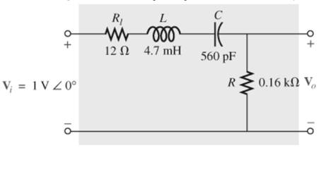
For the band-pass filter in Fig. 22.112
Want to see the full answer?
Check out a sample textbook solution
Chapter 22 Solutions
Laboratory Manual for Introductory Circuit Analysis


- The bandwidth of a receiver with a 75-V input resistance is 6 MHz.The temperature is 29°C. What is the input thermal noise voltage?arrow_forwardPlot the graph in semilog paper and Calculate the bandwidth from the grapharrow_forwardل توجد بطاقة Dچ Test_5.docx → For the given circuits and input waveform determine the output waveform 2.2 ko 20 5 1. a) -10- b) c) d)arrow_forward
- H.W: A resistor of resistance R=1000 2is maintained at 17 °C and it shunted by 100 uH inductor. Determine the ms noise voltage across the inductor over a frequency bandwi dth of: Ans: 182 x10° volt Ans: 9.22 x10 volt Ans: 2.34 x10 volt i) 15.9 kHz ii) i) 159 kHz 1590 kHzarrow_forward10 2 R=10 Vi Vo L=1mH C= 0.05 uF Figure 22.4 Figure 22.4 See Figure 22.4. This band-stop filter has a center frequency fo- At this frequency, what is Vo if V, is 10 V? О 1.0 V O 10.0 V O OV O 0.9 Varrow_forward3. Let Is= 50A, nd 20 40 10arrow_forward
- D4 - Calculate: 1-The value of Z that easures resonance and tlie value of the resonance frequency. 2-The value of Z that ensures maximum power transfer to Z and the value of this power. -j202 150 120 18: 20/75 v SoV 60/ 10arrow_forwardin bandpass filter create a simple analog signal and label it with 300 to 3khz.arrow_forwardA:11 A docs.google.com For positive half of the signal below, what is the peak output value of the circuit? NOTE: use silicon diode. * 20 V 10V -20 V O 3.3 O -10.3 50.7 29.3 32.3 like that of the clipper, the shape of the input signals of a clamper is changed. * O F От For the given circuit for a 40 V (p-p) sinusoidal input vi, what is the value of vi at which the clipping begIs: v-ov. NOTE: usearrow_forward
- Identify the type of filter. Depending on the type of filter ,calculate the resonant frequency or it's corner frequency.arrow_forwardQ Detelmine v. for Cach nebw ur of fyues below for the input shown sideal diuches v. -Vm vi R -Vm -Vm v cideal dinde)arrow_forwardJA 1 التاريخ 2K2 95: Indicate the type of filter that used in below circuit diagram and measure the cateff frequency with derive the transfer function and find Vo in volt? hello الموضوع : gook Voarrow_forward
 Introductory Circuit Analysis (13th Edition)Electrical EngineeringISBN:9780133923605Author:Robert L. BoylestadPublisher:PEARSON
 Delmar's Standard Textbook Of ElectricityElectrical EngineeringISBN:9781337900348Author:Stephen L. HermanPublisher:Cengage Learning
 Programmable Logic ControllersElectrical EngineeringISBN:9780073373843Author:Frank D. PetruzellaPublisher:McGraw-Hill Education
 Fundamentals of Electric CircuitsElectrical EngineeringISBN:9780078028229Author:Charles K Alexander, Matthew SadikuPublisher:McGraw-Hill Education
 Electric Circuits. (11th Edition)Electrical EngineeringISBN:9780134746968Author:James W. Nilsson, Susan RiedelPublisher:PEARSON
 Engineering ElectromagneticsElectrical EngineeringISBN:9780078028151Author:Hayt, William H. (william Hart), Jr, BUCK, John A.Publisher:Mcgraw-hill Education,