
Laboratory Manual for Introductory Circuit Analysis
13th Edition
ISBN: 9780133923780
Author: Robert L. Boylestad, Gabriel Kousourou
Publisher: PEARSON
expand_more
expand_more
format_list_bulleted
Concept explainers
Videos
Textbook Question
Chapter 22, Problem 37P
For the Butterworth filter of Fig. 22.118:
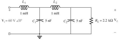
Fig. 22.118
- In words without any calculations, describe the network response to a wide range of frequencies.
- Plot the response of the filter to a range of frequencies extending from 0 Hz to 1 MHz.
Expert Solution & Answer
Want to see the full answer?
Check out a sample textbook solution
Students have asked these similar questions
22.21 Design an RC Low Pass Filter (LPF) to have a cut-off frequency of 500 Hz using a resistor (R) of 1.2 k2.
Sketch the resulting magnitude and phase plot for a frequency range of 0.1fo to 10fo.
Can we obtain a plot of XL against frequency f experimentally?
Harry plz
Chapter 22 Solutions
Laboratory Manual for Introductory Circuit Analysis
Ch. 22 - Determine the frequencies (in kHz) at the points...Ch. 22 - Determine log10 for each value of X. 100,000...Ch. 22 - Given N=log10 , determine for each value of N. 3...Ch. 22 - Determine loge for each value of X. a. 100,000 b....Ch. 22 - Determine log1048=log10(8)(6), and compare to...Ch. 22 - Determine log100.2=log1018/90, and compare to...Ch. 22 - Verify that log100.5 is equal to...Ch. 22 - Prob. 8PCh. 22 - Determine the number of bels that relate power...Ch. 22 - Prob. 10P
Ch. 22 - Prob. 11PCh. 22 - Determine the dBm level for an output power of...Ch. 22 - Find the dBu gain of an amplifier that raises the...Ch. 22 - Prob. 14PCh. 22 - If the sound pressure level is increased from...Ch. 22 - What is the required increase in acoustical power...Ch. 22 - Using semilog paper, plot XL versus frequency for...Ch. 22 - For the meter of Fig. 22.8, find the power...Ch. 22 - For the R-C low-pass filter in Fig. 22.105: Sketch...Ch. 22 - Prob. 20PCh. 22 - Design an R-Clow-pass filter to have a cutoff...Ch. 22 - For the low-pass filter in Fig. 22.107: Fig....Ch. 22 - For the R-C high-pass filter in Fig. 22.108:...Ch. 22 - For the network in Fig. 22.109: Determine...Ch. 22 - Design a high-pass R-C filter to have a cutoff or...Ch. 22 - For the high-pass filter in Fig. 22.110: Determine...Ch. 22 - For the band-pass filter in Fig. 22.111: Sketch...Ch. 22 - Design a band-pass filter such as the one...Ch. 22 - For the band-pass filter in Fig. 22.112...Ch. 22 - Prob. 30PCh. 22 - For the band-stop filter in Fig. 22.114: Determine...Ch. 22 - For the band-pass filter in Fig. 22.115: Determine...Ch. 22 - For the network in Fig. 22.45(a), if...Ch. 22 - Prob. 34PCh. 22 - For the low-pass T filter of Fig. 22.116: In...Ch. 22 - Prob. 36PCh. 22 - For the Butterworth filter of Fig. 22.118: Fig....Ch. 22 - Sketch the idealized Bode plot for Av=Vo/Vi for...Ch. 22 - Sketch the response of the magnitude of...Ch. 22 - Sketch the idealized Bode plot for Av=Vo/Vi for...Ch. 22 - Sketch the response of the magnitude of...Ch. 22 - Prob. 42PCh. 22 - Prob. 43PCh. 22 - For the filter in Fig. 22.125: Sketch the curve of...Ch. 22 - Prob. 45PCh. 22 - Prob. 46PCh. 22 - Prob. 47PCh. 22 - A bipolar transistor amplifier has the following...Ch. 22 - A transistor amplifier has a midband gain of 120,...Ch. 22 - Sketch the Bode plot of the following function:...Ch. 22 - Sketch the Bode plot of the following function:...Ch. 22 - Sketch the Bode plot of the following function:...Ch. 22 - Sketch the Bode plot of the following function:...Ch. 22 - Sketch the Bode plot of the following function...Ch. 22 - Prob. 56PCh. 22 - Using schematics, obtain the magnitude and phase...Ch. 22 - Using schematics, obtain the magnitude and phase...Ch. 22 - Prob. 59PCh. 22 - Prob. 60P
Knowledge Booster


Learn more about
Need a deep-dive on the concept behind this application? Look no further. Learn more about this topic, electrical-engineering and related others by exploring similar questions and additional content below.Similar questions
- Please answer fast I'll ratearrow_forwardCan you upload a schematic of ne5532 audio amplifier circuit with a gain of one? And explain your circuitarrow_forwardApproximately, determine the Vpp and frequency of the given signal: Reading settings: 20V/DIV and 5ms/DIV Explain your approximationarrow_forward
- Find the minimum sampling frequency for the bandpass signal whose frequency spectrum is given in the figure. plot the frequency spectrum of the sampled signalarrow_forwardQ.2:- a) Explain what a band-pass filter is, and how it differs from either a low-pass or a high-pass filter circuit. Also, explain what a hand-stop filter is, and draw Bode plots representative of both band-pass and band-stop filter types. b) What is the purpose (ll) of the parity bit during data transmission?arrow_forward4kHz audio signal with a 40000kHz carrier in a nonlinear circuitFind all the frequency components obtained at the output when mixed?arrow_forward
- For a signal in the range of 6 to 63, in order to have a resolution of 0.17, we need . Select one: O a. 337 Оь. 338 Oc. 333arrow_forwardExplain the cases why tuned filters or detuned filters are used in power distribution system. Give example of tuning frequencies for tuned and detuned filters. Draw the impedance - frequency curves of the passive harmonic filters in accordance with your example frequencies.arrow_forwardSubject: Mechanical Measurements Do not copy other online answersarrow_forward
arrow_back_ios
SEE MORE QUESTIONS
arrow_forward_ios
Recommended textbooks for you
 Introductory Circuit Analysis (13th Edition)Electrical EngineeringISBN:9780133923605Author:Robert L. BoylestadPublisher:PEARSON
 Delmar's Standard Textbook Of ElectricityElectrical EngineeringISBN:9781337900348Author:Stephen L. HermanPublisher:Cengage Learning
 Programmable Logic ControllersElectrical EngineeringISBN:9780073373843Author:Frank D. PetruzellaPublisher:McGraw-Hill Education
 Fundamentals of Electric CircuitsElectrical EngineeringISBN:9780078028229Author:Charles K Alexander, Matthew SadikuPublisher:McGraw-Hill Education
 Electric Circuits. (11th Edition)Electrical EngineeringISBN:9780134746968Author:James W. Nilsson, Susan RiedelPublisher:PEARSON
 Engineering ElectromagneticsElectrical EngineeringISBN:9780078028151Author:Hayt, William H. (william Hart), Jr, BUCK, John A.Publisher:Mcgraw-hill Education,
Introductory Circuit Analysis (13th Edition)
Electrical Engineering
ISBN:9780133923605
Author:Robert L. Boylestad
Publisher:PEARSON
Delmar's Standard Textbook Of Electricity
Electrical Engineering
ISBN:9781337900348
Author:Stephen L. Herman
Publisher:Cengage Learning
Programmable Logic Controllers
Electrical Engineering
ISBN:9780073373843
Author:Frank D. Petruzella
Publisher:McGraw-Hill Education
Fundamentals of Electric Circuits
Electrical Engineering
ISBN:9780078028229
Author:Charles K Alexander, Matthew Sadiku
Publisher:McGraw-Hill Education
Electric Circuits. (11th Edition)
Electrical Engineering
ISBN:9780134746968
Author:James W. Nilsson, Susan Riedel
Publisher:PEARSON
Engineering Electromagnetics
Electrical Engineering
ISBN:9780078028151
Author:Hayt, William H. (william Hart), Jr, BUCK, John A.
Publisher:Mcgraw-hill Education,
What is Filter & Classification of Filters | Four Types of Filters | Electronic Devices & Circuits; Author: SimplyInfo;https://www.youtube.com/watch?v=9x1Sjz-VPSg;License: Standard Youtube License