
Introductory Circuit Analysis; Laboratory Manual For Introductory Circuit Analysis Format: Kit/package/shrinkwrap
13th Edition
ISBN: 9780134297446
Author: Boylestad, Robert L.
Publisher: Prentice Hall
expand_more
expand_more
format_list_bulleted
Concept explainers
Videos
Textbook Question
Chapter 22, Problem 40P
- Sketch the idealized Bode plot for
- for the low-pass filter in Fig. 22.121.
- Using the results of part (a), sketch the actual frequency response for the same frequency range.
- Determine the decibel level at
- Determine the gain
- Sketch the phase response for the same frequency range.
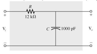 Fig. 22.121
Expert Solution & Answer
Want to see the full answer?
Check out a sample textbook solution
Students have asked these similar questions
Calculate the channel capacity of the system if its bandwidth is 200kHz at a temperature of 10 °C and its signal power is 120 uW
calculate both quality factor Q and resonance frequency if it exists
3)
The fidelity of a receiver is better if its RF and IF stages have more bandwidth.
Select one: True
False
Chapter 22 Solutions
Introductory Circuit Analysis; Laboratory Manual For Introductory Circuit Analysis Format: Kit/package/shrinkwrap
Ch. 22 - Determine the frequencies (in kHz) at the points...Ch. 22 - Determine log10 for each value of X. 100,000...Ch. 22 - Given N=log10 , determine for each value of N. 3...Ch. 22 - Determine loge for each value of X. a. 100,000 b....Ch. 22 - Determine log1048=log10(8)(6), and compare to...Ch. 22 - Determine log100.2=log1018/90, and compare to...Ch. 22 - Verify that log100.5 is equal to...Ch. 22 - Prob. 8PCh. 22 - Determine the number of bels that relate power...Ch. 22 - Prob. 10P
Ch. 22 - Prob. 11PCh. 22 - Determine the dBm level for an output power of...Ch. 22 - Find the dBu gain of an amplifier that raises the...Ch. 22 - Prob. 14PCh. 22 - If the sound pressure level is increased from...Ch. 22 - What is the required increase in acoustical power...Ch. 22 - Using semilog paper, plot XL versus frequency for...Ch. 22 - For the meter of Fig. 22.8, find the power...Ch. 22 - For the R-C low-pass filter in Fig. 22.105: Sketch...Ch. 22 - Prob. 20PCh. 22 - Design an R-Clow-pass filter to have a cutoff...Ch. 22 - For the low-pass filter in Fig. 22.107: Fig....Ch. 22 - For the R-C high-pass filter in Fig. 22.108:...Ch. 22 - For the network in Fig. 22.109: Determine...Ch. 22 - Design a high-pass R-C filter to have a cutoff or...Ch. 22 - For the high-pass filter in Fig. 22.110: Determine...Ch. 22 - For the band-pass filter in Fig. 22.111: Sketch...Ch. 22 - Design a band-pass filter such as the one...Ch. 22 - For the band-pass filter in Fig. 22.112...Ch. 22 - Prob. 30PCh. 22 - For the band-stop filter in Fig. 22.114: Determine...Ch. 22 - For the band-pass filter in Fig. 22.115: Determine...Ch. 22 - For the network in Fig. 22.45(a), if...Ch. 22 - Prob. 34PCh. 22 - For the low-pass T filter of Fig. 22.116: In...Ch. 22 - Prob. 36PCh. 22 - For the Butterworth filter of Fig. 22.118: Fig....Ch. 22 - Sketch the idealized Bode plot for Av=Vo/Vi for...Ch. 22 - Sketch the response of the magnitude of...Ch. 22 - Sketch the idealized Bode plot for Av=Vo/Vi for...Ch. 22 - Sketch the response of the magnitude of...Ch. 22 - Prob. 42PCh. 22 - Prob. 43PCh. 22 - For the filter in Fig. 22.125: Sketch the curve of...Ch. 22 - Prob. 45PCh. 22 - Prob. 46PCh. 22 - Prob. 47PCh. 22 - A bipolar transistor amplifier has the following...Ch. 22 - A transistor amplifier has a midband gain of 120,...Ch. 22 - Sketch the Bode plot of the following function:...Ch. 22 - Sketch the Bode plot of the following function:...Ch. 22 - Sketch the Bode plot of the following function:...Ch. 22 - Sketch the Bode plot of the following function:...Ch. 22 - Sketch the Bode plot of the following function...Ch. 22 - Prob. 56PCh. 22 - Using schematics, obtain the magnitude and phase...Ch. 22 - Using schematics, obtain the magnitude and phase...Ch. 22 - Prob. 59PCh. 22 - Prob. 60P
Knowledge Booster


Learn more about
Need a deep-dive on the concept behind this application? Look no further. Learn more about this topic, electrical-engineering and related others by exploring similar questions and additional content below.Similar questions
- 4) If the Noise Ratio of a receiver is 1, then the SNR at the output will be equal to the SNR at the input . Select one: True Falsearrow_forwardThe equivalent noise temperature of an amplifier is 40 K. Find the noise factor at room temperature of 298 K.arrow_forwardWhat is the information capacity of telephone circuit with a S/N of 30dB and a bandwidth of 2.7KHz?arrow_forward
- Suppose the noise power at the input to a receiver is 5 nW in the bandwidth of interest. What would be the required signal power for signal–to–noise ratio of 30 dB? full solution thank you for the help!arrow_forwardFor the Bode plot shown below, determine: Whether the system is stable: The gain margin: And the phase margin.arrow_forwardConsider a lead network with a lower frequency break of 800 Hz. Calculate the frequency at which the gain will be -24.6 dB?arrow_forward
- The noise equivalent power of a detector with an area of 2 cm2 is measured to be 2 × 10⁻⁸ watts/(Hz)1/2 with a bandwidth of 1 Hz. What power is incident on the detector if the ratio of the noise voltage to the signal voltage is 10-5? (Show your calculation)arrow_forwardAMPLIFIER'S FREQUENCY RESPONSE 16arrow_forwardAt w = 10^3 rad/sec, find the input admittance of the circuitarrow_forward
- If the angle is between , that means that active power is flowing from sending end to receiving end.arrow_forwardA transmitter has a directional antenna with a gain of 4 dB. The frequency is 72 MHz. The power into the antenna is 2 W. The receiver uses a one-quarter wavelength ground plane. The distance between the transmitting and receiving antennas is 3 mi. What is the power at the receiver? What is the receiver input voltage with a 50-V input impedance?arrow_forwardDetermine the total noise figure referred to the input of a mixer stage that has a noise figure of 20 dB proceeded by an amplifier that has a noise figure of 8 dB and an available power gain of 25 dB A. 2.18 dB B. 2.81 dB. C. 1.28 dB D. 8.21 dBarrow_forward
arrow_back_ios
SEE MORE QUESTIONS
arrow_forward_ios
Recommended textbooks for you
 Introductory Circuit Analysis (13th Edition)Electrical EngineeringISBN:9780133923605Author:Robert L. BoylestadPublisher:PEARSON
 Delmar's Standard Textbook Of ElectricityElectrical EngineeringISBN:9781337900348Author:Stephen L. HermanPublisher:Cengage Learning
 Programmable Logic ControllersElectrical EngineeringISBN:9780073373843Author:Frank D. PetruzellaPublisher:McGraw-Hill Education
 Fundamentals of Electric CircuitsElectrical EngineeringISBN:9780078028229Author:Charles K Alexander, Matthew SadikuPublisher:McGraw-Hill Education
 Electric Circuits. (11th Edition)Electrical EngineeringISBN:9780134746968Author:James W. Nilsson, Susan RiedelPublisher:PEARSON
 Engineering ElectromagneticsElectrical EngineeringISBN:9780078028151Author:Hayt, William H. (william Hart), Jr, BUCK, John A.Publisher:Mcgraw-hill Education,
Introductory Circuit Analysis (13th Edition)
Electrical Engineering
ISBN:9780133923605
Author:Robert L. Boylestad
Publisher:PEARSON
Delmar's Standard Textbook Of Electricity
Electrical Engineering
ISBN:9781337900348
Author:Stephen L. Herman
Publisher:Cengage Learning
Programmable Logic Controllers
Electrical Engineering
ISBN:9780073373843
Author:Frank D. Petruzella
Publisher:McGraw-Hill Education
Fundamentals of Electric Circuits
Electrical Engineering
ISBN:9780078028229
Author:Charles K Alexander, Matthew Sadiku
Publisher:McGraw-Hill Education
Electric Circuits. (11th Edition)
Electrical Engineering
ISBN:9780134746968
Author:James W. Nilsson, Susan Riedel
Publisher:PEARSON
Engineering Electromagnetics
Electrical Engineering
ISBN:9780078028151
Author:Hayt, William H. (william Hart), Jr, BUCK, John A.
Publisher:Mcgraw-hill Education,
What is Filter & Classification of Filters | Four Types of Filters | Electronic Devices & Circuits; Author: SimplyInfo;https://www.youtube.com/watch?v=9x1Sjz-VPSg;License: Standard Youtube License