Concept explainers
(a)
The current induced in the aluminum ring
(a)
Answer to Problem 5P
A current of
Explanation of Solution
Write the equation for the emf generated in the coil.
Here,
Here,
Write the equation for the magnetic field due to the solenoid.
Here,
Substitute
Write the equation for the area of the coil.
Here,
Substitute equation (VI) in equation (V).
The ring is placed at one end of a solenoid. The field in the end of the solenoid is half the field at the center of the solenoid. Write the equation for the emf induced in the ring.
Substitute
Write the equation for the current induced in the ring.
Conclusion:
Substitute
Therefore, the current induced in the ring is
(b)
The magnitude of magnetic field in the ring
(b)
Answer to Problem 5P
The induced current produces a magnetic field of
Explanation of Solution
Write the equation for the magnetic field produced in the ring.
Here,
Conclusion:
Substitute
Therefore, the induced current produces a magnetic field of
(c)
The direction of magnetic field in the ring
(c)
Answer to Problem 5P
The magnetic field in the ring points towards the left
Explanation of Solution
Figure (I) shows the direction of the magnetic field in the solenoid.
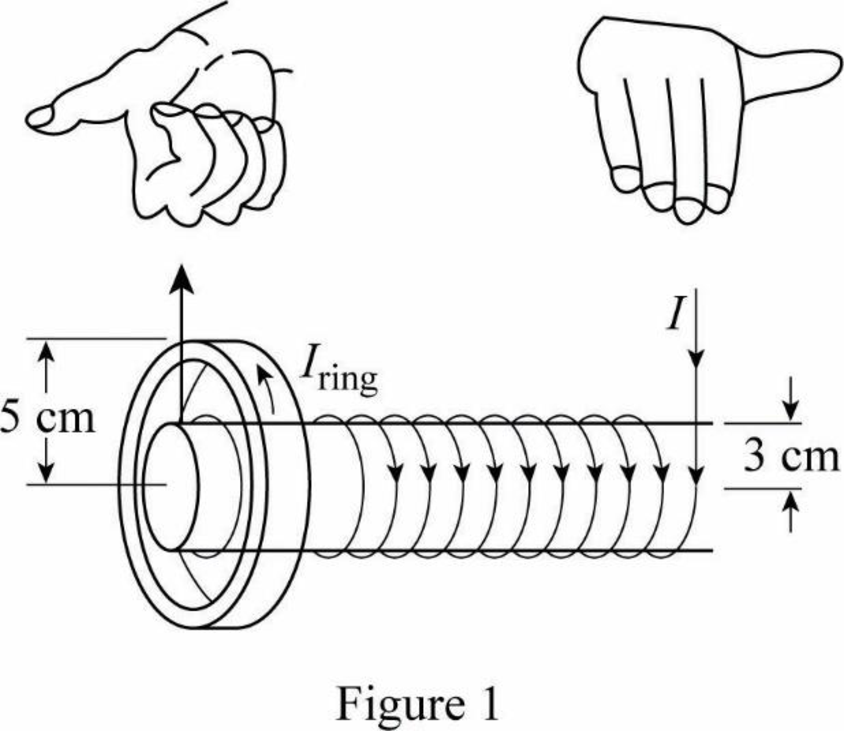
The magnetic field of the solenoid points to the right as shown in figure.1. Therefore, the magnetic field at the center of the ring acts towards the left in order to oppose the increasing field.
Conclusion:
Therefore, the magnetic field in the ring acts towards the left.
Want to see more full solutions like this?
Chapter 23 Solutions
Principles of Physics


- An aluminum ring of radius r1 = 5.00 cm and resistance 3.00 104 is placed around one end of a long air-core solenoid with 1 000 turns per meter and radius r2 = 3.00 cm as shown in Figure P30.5. Assume the axial component of the field produced by the solenoid is one-half as strong over the area of the end of the solenoid as at the center of the solenoid. Also assume the solenoid produces negligible field outside its cross-sectional area. The current in the solenoid is increasing at a rate of 270 A/s. (a) What is the induced current in the ring? At the center of the ring, what are (b) the magnitude and (c) the direction of the magnetic field produced by the induced current in the ring? Figure P30.5 Problems 5 and 6.arrow_forwardWhy is the following situation impossible? A conducting rectangular loop of mass M = 0.100 kg, resistance R = 1.00 , and dimensions w = 50.0 cm by = 90.0 cm is held with its lower edge just above a region with a uniform magnetic field of magnitude B = 1.00 T as shown in Figure P30.34. The loop is released from rest. Just as the top edge of the loop reaches the region containing the field, the loop moves with a speed 4.00 m/s. Figure P30.34arrow_forward(a) A solenoid is formed of a length of wire that carries a constant current 1.The solenoid has 74 turns of wire per cm. The magnetic field at the center of the solenoid is measured to be 25 G. The current through the solenoid in (A): (b) A length of wire is formed into a solenoid with n turns of wire per millimetre. The wire carries a constant current 1. The magnetic field at the center of the solenoid is B. Thearrow_forward
- The current I through a long solenoid with n turns per meter and radius 0.30m is changing with time as given by I=sin(120t). The magnetic field inside a solenoid is given by B=nμ0I where μ0 is the free space permeability μ0=1.26·10−6 H/m. What is the magnetic flux through a single coil at a time of t= 1.1 s at distance r= 0.22 m from the center of the solenoid if there are, n=119 turns/m? a) Start by determining the flux through a gaussian loop of radius r=0.22 m centered in the middle of the solenoid. b) Next determine the rate of change of the magnetic flux with timearrow_forwardTwo conductors are perpendicular to each other and carry electric currents I1 and I2. Take I1 = 5.00 A; I2 = 6.00 A, x = 3.00 m and y = 4.00 m. 1. Calculate the magnitude of the induced magnetic field at point P with the coordinates (x, y) due to I1. 2. The direction of the magnetic field at point P due to I1 is 3. Calculate the magnitude of the induced magnetic field at point P with the coordinates (x, y) due to I2. 4. The direction of the magnetic field at point P due to I2 is 5. Calculate the magnitude of the resultant induced magnetic field at point P with the coordinates (x, y) due to both conductors. 6. The direction of the magnetic field at point P due to I2 isarrow_forwardA rectangular toroid with inner radius R1 = 7.0 cm, outer radius R2 = 9.0 cm , height h = 3.0 , and N = 3000 turns is filled with an iron core of magneticsusceptibility 5.2 × 10³ . (a) What is the self-inductance of the toroid? (b) If the current through the toroid is 2.0 A, what is the magnetic field at the center of the core? (c) For this same 2.0-A current, what is the effective surface current formed by the aligned atomic current loops in the iron core?arrow_forward
- Figure P23.15 shows a top view of a bar that can slide on two frictionless rails. The resistor is R = 6.00 , and a 2.50-T magnetic field is directed perpendicularly downward, into the paper. Let = 1.20 m. (a) Calculate the applied force required to move the bar to the right at a constant speed of 2.00 m/s. (b) At what rate is energy delivered to the resistor? Figure P23.15 Problems 15 through 18.arrow_forwardA piece of insulated wire is shaped into a figure eight as shown in Figure P23.12. For simplicity, model the two halves of the figure eight as circles. The radius of the upper circle is 5.00 cm and that of the lower circle is 9.00 cm. The wire has a uniform resistance per unit length of 3.00 Ω/m. A uniform magnetic field is applied perpendicular to the plane of the two circles, in the direction shown. The magnetic field is increasing at a constant rate of 2.00 T/s. Find (a) the magnitude and (b) the direction of the induced current in the wire. Figure P23.12arrow_forwardA wire is bent in the form of a square loop with sides of length L (Fig. P30.24). If a steady current I flows in the loop, determine the magnitude of the magnetic field at point P in the center of the square. FIGURE P30.24arrow_forward
- A rectangular conducting loop with dimensions w = 32.0 cm and h = 78.0 cm is placed a distance a = 5.00 cm from a long, straight wire carrying current I = 7.00 A in the downward direction (Fig. P32.75). a. What is the magnitude of the magnetic flux through the loop? b. If the current in the wire is increased linearly from 7.00 A to 15.0 A in 0.230 s, what is the magnitude of the induced emf in the loop? c. What is the direction of the current that is induced in the loop during this time interval?arrow_forwardThe homopolar generator, also called the Faraday disk, is a low-voltage, high-current electric generator. It consists of a rotating conducting disk with one stationary brush (a sliding electrical contact) at its axle and another at a point on its circumference as shown in Figure P23.21. A uniform magnetic field is applied perpendicular to the plane of the disk. Assume the field is 0.900 T, the angular speed is 3.20 103 rev/min, and the radius of the disk is 0.400 m. Find the emf generated between the brushes. When superconducting coils are used to produce a large magnetic field, a homopolar generator can have a power output of several megawatts. Such a generator is useful, for example, in purifying metals by electrolysis. If a voltage is applied to the output terminals of the generator, it runs in reverse as a homopolar motor capable of providing great torque, useful in ship propulsion.arrow_forward
 Principles of Physics: A Calculus-Based TextPhysicsISBN:9781133104261Author:Raymond A. Serway, John W. JewettPublisher:Cengage Learning
 Physics for Scientists and Engineers with Modern ...PhysicsISBN:9781337553292Author:Raymond A. Serway, John W. JewettPublisher:Cengage Learning
 Physics for Scientists and Engineers: Foundations...PhysicsISBN:9781133939146Author:Katz, Debora M.Publisher:Cengage Learning
 Physics for Scientists and EngineersPhysicsISBN:9781337553278Author:Raymond A. Serway, John W. JewettPublisher:Cengage Learning