
Videos
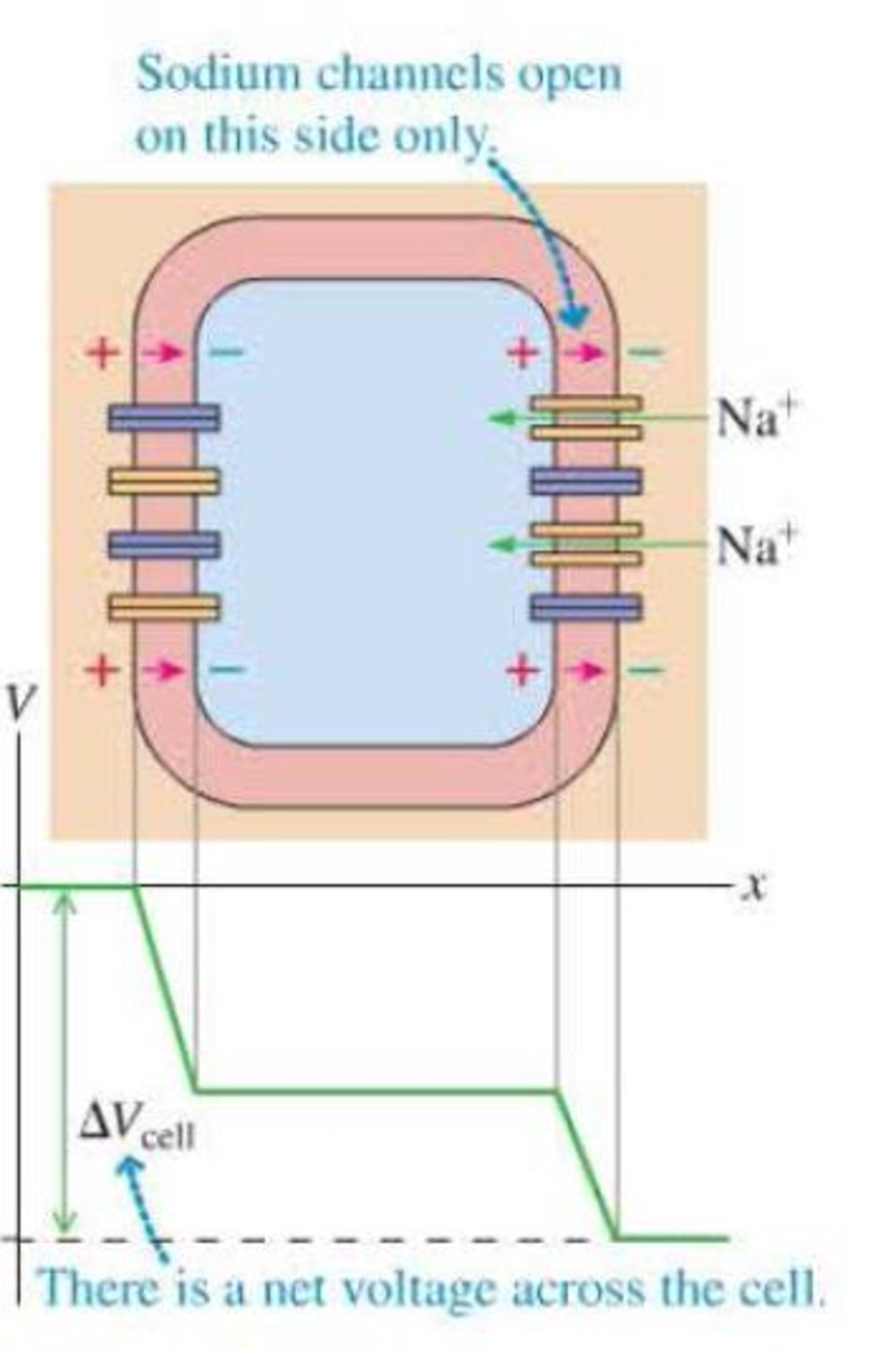
The voltage produced by a single nerve or muscle cell is quite small, but there are many species of fish that use multiple action potentials in series to produce significant voltages. The electric organs in these fish are composed of specialized disk-shaped cells called electrocytes. The cell at rest has the usual potential difference between the inside and the outside, but the net potential difference across the cell is zero. An electrocyte is connected to nerve fibers that initially trigger a depolarization in one side of the cell but not the other. For the very short time of this depolarization, there is a net potential difference across the cell, as shown in Figure P23.86. Stacks of these cells connected in series can produce a large total voltage. Each stack can produce a small current; for more total current, more stacks are needed, connected in parallel.
Figure P23.86
Electric eels live in fresh water. The torpedo ray is an electric fish that lives in salt water. The electrocytes in the ray are grouped differently than in the eel; each stack of electrocytes has fewer cells, but there are more stacks in parallel. Which of the following best explains the ray’s electrocyte arrangement?
A. The lower resistivity of salt water requires more current but lower voltage.
B. The lower resistivity of salt water requires more voltage but lower current.
C. The higher resistivity of salt water requires more current but lower voltage.
D. The higher resistivity of salt water requires more voltage but lower current.
Want to see the full answer?
Check out a sample textbook solution
Chapter 23 Solutions
Student Solutions Manual Volume 1 (chs 1-16) For College Physics: A Strategic Approach
Additional Science Textbook Solutions
Introduction to Electrodynamics
The Cosmic Perspective (8th Edition)
Cosmic Perspective Fundamentals
University Physics (14th Edition)
The Cosmic Perspective Fundamentals (2nd Edition)
University Physics with Modern Physics (14th Edition)


- A Pairs of parallel wires or coaxial cables are two conductors separated by an insulator, so they have a capacitance. For a given cable, the capacitance is independent of the length if the cable is very long. A typical circuit model of a cable is shown in Figure P27.87. It is called a lumped-parameter model and represents how a unit length of the cable behaves. Find the equivalent capacitance of a. one unit length (Fig. P27.87A), b. two unit lengths (Fig. P27.87B), and c. an infinite number of unit lengths (Fig. P27.87C). Hint: For the infinite number of units, adding one more unit at the beginning does not change the equivalent capacitance.arrow_forwardIn Figure P27.7, capacitor 1 (C1 = 20.0 F) initially has a potential difference of 50.0 V and capacitor 2 (C2 = 5.00 F) has none. The switches are then closed simultaneously. a. Find the final charge on each capacitor after a long time has passed. b. Calculate the percentage of the initial stored energy that was lost when the switches were closed. FIGURE P27.7arrow_forwardConsider the circuit shown in Figure P20.52, where C1 = 6.00 F, C2 = 3.00 F, and V = 20.0 V. Capacitor C1 is first charged by closing switch S1. Switch S1 is then opened, and the charged capacitor is connected to the uncharged capacitor by closing S2. Calculate (a) the initial charge acquired by C1 and (b) the final charge on each capacitor. Figure P20.52arrow_forward
- (a) Calculate the potential difference between points a and b in Figure P27.37 and (b) identify which point is at the higher potential. Figure P27.37arrow_forwardConsider the circuit shown in Figure P26.24, where C1, = 6.00 F, C2 = 3.00 F. and V = 20.0 V. Capacitor C1 is first charged by closing switch S1. Switch S1 is then opened, and the charged capacitor is connected to the uncharged capacitor by closing Calculate (a) the initial charge acquired by C, and (b) the final charge on each capacitor.arrow_forwardReferring to Figure CQ21.4, describe what happens to the light-bulb after the switch is closed. Assume the capacitor has a large capacitance and is initially uncharged. Also assume the light illuminates when connected directly across the battery terminals.arrow_forward
- An oceanographer is studying how the ion concentration in seawater depends on depth. She makes a measurement by lowering into the water a pair of concentric metallic cylinders (Fig. P21.66) at the end of a cable and taking data to determine the resistance between these electrodes as a function of depth. The water between the two cylinders forms a cylindrical shell of inner radius ra, outer radius rb, and length L much larger than rb. The scientist applies a potential difference V between the inner and outer surfaces, producing an outward radial current I. Let represent the resistivity of the water. (a) Find the resistance of the water between the cylinders in terms of L, , ra, an rb. (b) Express the resistivity of the water in terms of the measured quantities L, ra, rb, V, and I. Figure P21.66arrow_forwardAssume a length of axon membrane of about 0.10 m is excited by an action potential (length excited = nerve speed pulse duration = 50.0 m/s 2.0 103 s = 0.10 m). In the resting state, the outer surface of the axon wall is charged positively with K+ ions and the inner wall has an equal and opposite charge of negative organic ions, as shown in Figure P18.43. Model the axon as a parallel-plate capacitor and take C = 0A/d and Q = C V to investigate the charge as follows. Use typical values for a cylindrical axon of cell wall thickness d = 1.0 108 m, axon radius r = 1.0 101 m, and cell-wall dielectric constant = 3.0. (a) Calculate the positive charge on the outside of a 0.10-m piece of axon when it is not conducting an electric pulse. How many K+ ions are on the outside of the axon assuming an initial potential difference of 7.0 102 V? Is this a large charge per unit area? Hint: Calculate the charge per unit area in terms of electronic charge e per squared (2). An atom has a cross section of about 1 2 (1 = 1010 m). (b) How much positive charge must flow through the cell membrane to reach the excited state of + 3.0 102 V from the resting state of 7.0 102 V? How many sodium ions (Na+) is this? (c) If it takes 2.0 ms for the Na+ ions to enter the axon, what is the average current in the axon wall in this process? (d) How much energy does it take to raise the potential of the inner axon wall to + 3.0 102 V, starting from the resting potential of 7.0 102 V? Figure P18.43 Problem 43 and 44.arrow_forwardFour parallel metal plates P1, P2, P3, and P4, each of area 7.50 cm2, are separated successively by a distance d = 1.19 mm as shown in Figure P25.34. Plate P1 is connected to the negative terminal of a battery, and P2 is connected to the positive terminal. The battery maintains a potential difference of 12.0 V. (a) If P3 is connected to the negative terminal, what is the capacitance of the three-plate system P1P2P3? (b) What is the charge on P2? (c) If P4 is now connected to the positive terminal, what is the capacitance of the four-plate system P1P2P3P4? (d) What is the charge on P4?arrow_forward
- A capacitor stores charge Q at a potential difference V. What happens if the voltage applied to a capacitor by a battery is doubled to 2 V? (a) The capacitance falls to half its initial value, and the charge remains the same. (b) The capacitance and the charge both fall to half their initial values. (c) The capacitance and the charge both double. (d) The capacitance remains the same, and the charge doubles.arrow_forwardA charge Q is placed on a capacitor of capacitance C. The capacitor is connected into the circuit shown in Figure P26.37, with an open switch, a resistor, and an initially uncharged capacitor of capacitance 3C. The switch is then closed, and the circuit comes to equilibrium. In terms of Q and C, find (a) the final potential difference between the plates of each capacitor, (b) the charge on each capacitor, and (c) the final energy stored in each capacitor. (d) Find the internal energy appearing in the resistor. Figure P26.37arrow_forwardAccording to its design specification, the timer circuit delaying the closing of an elevator door is to have a capacitance of 32.0 F between two points A and B. When one circuit is being constructed, the inexpensive but durable capacitor installed between these two points is found to have capacitance 34.8 F. To meet the specification, one additional capacitor can be placed between the two points. (a) Should it be in series or in parallel with the 34.8-F capacitor? (b) What should be its capacitance? (c) What If? The next circuit comes down the assembly line with capacitance 29.8 F between A and B. To meet the specification, what additional capacitor should be installed in series or in parallel in that circuit?arrow_forward
 Principles of Physics: A Calculus-Based TextPhysicsISBN:9781133104261Author:Raymond A. Serway, John W. JewettPublisher:Cengage Learning
 College PhysicsPhysicsISBN:9781305952300Author:Raymond A. Serway, Chris VuillePublisher:Cengage Learning
 Physics for Scientists and EngineersPhysicsISBN:9781337553278Author:Raymond A. Serway, John W. JewettPublisher:Cengage Learning
 Physics for Scientists and Engineers with Modern ...PhysicsISBN:9781337553292Author:Raymond A. Serway, John W. JewettPublisher:Cengage Learning
 Physics for Scientists and Engineers: Foundations...PhysicsISBN:9781133939146Author:Katz, Debora M.Publisher:Cengage Learning
 College PhysicsPhysicsISBN:9781285737027Author:Raymond A. Serway, Chris VuillePublisher:Cengage Learning