
Introductory Circuit Analysis; Laboratory Manual For Introductory Circuit Analysis Format: Kit/package/shrinkwrap
13th Edition
ISBN: 9780134297446
Author: Boylestad, Robert L.
Publisher: Prentice Hall
expand_more
expand_more
format_list_bulleted
Concept explainers
Videos
Textbook Question
Chapter 24, Problem 28P
The phase sequence for the
a. Find the angles
b. Find the voltage across each phase impedance in phasor form.
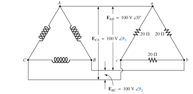
c. Draw the phasor diagram of the voltages found in part (b), and show that their phasor sum is zero around the close loop of the
d. Find the current through each phase impedance in phasor form.
e. Find the magnitude of the line currents.
Expert Solution & Answer
Want to see the full answer?
Check out a sample textbook solution
Students have asked these similar questions
31. A 3-phase 3-wire star-connected load consists of a capacitive reactance of 100ohm in the red phase and a resistor of 100ohm in Bo- each of the other phases. The line voltage is 440 V and the phase sequence is RYB. If the power is measured by the 2-wattmeter method,the current coils being connected in the red and yellow leads respectively, determine the reading of each instrument. (-86.5 W, 1.640 W) Answer
A three-phase transmission line has resistance and inductive reactance of 25V and 90V, respectively. With no load at the receiving end, a synchronous compensator there takes a current lagging by 90; the voltage is 145 kV at the sending end and 132 kV at the receiving end. Calculate the value of the current taken by the compensator.
When the load at the receiving end is 50MW, it is found that the line can operate with unchanged voltages at the sending and receiving ends, provided that the compensator takes the same current as before, but now leading by 90. Calculate the reactive power of the load
Q6:
i)
Which of the following is true for a transmission line under load?
Power factor at both the sending and receiving end will be equal
Reactive Power at both the sending and receiving end will be equal.
Active Power at the sending end will be greater than the active power at the receiving end.
Line current in the sending end will be equal to the line current at the receiving end
ii)
A transmission line has 80% efficiency when delivering 500 KW power to a 3-phase load at the receiving end. This implies that ______.
Voltage regulation of the line is 20%
Active power at the receiving side 375 kw/phase
Active power at the sending end is 500 kw/phase
Total power loss in the transmission line is 125 kW
iii)
Which of the following is true for transmission line under no-load?
Power factor at the sending end will be unity
Active Power at the…
Chapter 24 Solutions
Introductory Circuit Analysis; Laboratory Manual For Introductory Circuit Analysis Format: Kit/package/shrinkwrap
Ch. 24 - A balanced V load having a 10 resistance in each...Ch. 24 - Repeat Problem 1 if each phase impedance is...Ch. 24 - Repeat Problem 1 if each phase impedance is...Ch. 24 - The phase sequence for the Y-Y system in Fig....Ch. 24 - Repeat Problem 4 if each phase impedance are...Ch. 24 - Repeat Problem 4 if each phase impedance is...Ch. 24 - For the system in Fig. 24.43, find the magnitude...Ch. 24 - Computer the magnitude of the voltage EAB for the...Ch. 24 - For the Y-Y system in Fig. 24.45: a. Find the...Ch. 24 - For the Y-Y system of Fig. 24.46 the impedance of...
Ch. 24 - A balanced load having a 20 resistance in each...Ch. 24 - Repeat Problem 11 if each phase impedance is...Ch. 24 - Repeat Problem 11 if each phase impedance is...Ch. 24 - The phase sequence for the Y- system in Fig....Ch. 24 - Repeat Problem 14 if each phase impedance is...Ch. 24 - Repeat Problem 14 if each phase impedance are...Ch. 24 - Prob. 17PCh. 24 - For the connected load in Fig. 24.49: a. Find the...Ch. 24 - A balanced V load having a 30 resistance in each...Ch. 24 - Repeat Problem 19 if each phase impedance is...Ch. 24 - Prob. 21PCh. 24 - Prob. 22PCh. 24 - Prob. 23PCh. 24 - Repeat Problem 22 if each phase impedance is...Ch. 24 - Prob. 25PCh. 24 - Prob. 26PCh. 24 - Prob. 27PCh. 24 - The phase sequence for the - system in Fig....Ch. 24 - Repeat Problem 28 if each phase impedance is...Ch. 24 - Repeat Problem 28 if each phase impedance is...Ch. 24 - Prob. 31PCh. 24 - Prob. 32PCh. 24 - Prob. 33PCh. 24 - Find the total watts, volt-amperes reactive,...Ch. 24 - Prob. 35PCh. 24 - Find the total watts, volt-amperes reactive,...Ch. 24 - Find the total watts, volt-amperes reactive,...Ch. 24 - Prob. 38PCh. 24 - Prob. 39PCh. 24 - Find the total watts, volt-amperes reactive,...Ch. 24 - A balanced, three-phase, -connected load has a...Ch. 24 - A balanced, three-phase, Y-connected load has a...Ch. 24 - Find the total watts, volt-amperes reactive,...Ch. 24 - The Y-Y system in Fig. 24.53 has a balanced load...Ch. 24 - Prob. 45PCh. 24 - Prob. 46PCh. 24 - Repeat Problem 46 for the network in Fig. 24.47.Ch. 24 - For the three-wire system in Fig. 24.55, properly...Ch. 24 - Sketch three different ways that two wattmeters...Ch. 24 - For the Y- system in Fig. 24.56: Determine the...Ch. 24 - For the system in Fig. 24.57: Calculate the...Ch. 24 - For the three-phase, three-wire system in Fig....
Knowledge Booster


Learn more about
Need a deep-dive on the concept behind this application? Look no further. Learn more about this topic, electrical-engineering and related others by exploring similar questions and additional content below.Similar questions
- A balanced Y-connected load is connected to 3-phase transmission lines with line-to-line voltages of 21.5 kV. The current in each line is 75 A. What are the phase impedances of the Y-connected load?arrow_forward30. A 30-Y-connected load is connected between three line terminals, R, Y, B, the impedances (in ohms) of the load being: (I + 2) between R and the star point. (2+3) between Y and the star point and (3+j4) between B and the star point. The phase sequence is RYB. If the line voltage is 400 V, calculate the voltage between R and the star point. [181 V]arrow_forwardA balanced delta-connected load with impedance (25.98 + j15) ohms per phase is connected to a 3-phase, 3-wire, 250-V system by conductors having an impedance of (0.4 + j0.3) ohms per conductor. Find the line to line voltage at the load.arrow_forward
- Show the graph Three unbalanced DELTA connected loads are connected across a balanced source of 220 volts line to line. If Zab = 11 ∠30 Ω, Zbc = 22 ∠-30 Ω, and Zca = 22 Ω, calculate: a. Phase currents b. Line currentsarrow_forwardIn a 3-phase star connected system, prove that VL =square root of 3 Vph , by considering the line voltage (VBR = VB - VR ) with the help of necessary phasor diagram.arrow_forwardA balanced Y - connected load having a 25 Ω resistance in each leg is connected to a three -phase , four wires, Y-connected ABC sequence AC generator, if the line volatge EAB=, calculate 1. The phase voltages of the generator 2. The phase voltages of the load 3. The phase currents of the load 4. The line currentsarrow_forward
- 12) If Vab = 223 Vrms in a balanced Y-connected three-phase generator, find the magnitude of the phase-c voltage (in Vrms), assuming the phase sequence is acb.arrow_forwardA three phase transmission line has a resistance of 10 Ω and reactance of 80 Ω per wire. The load current is 90 A and the power factor of the load is 80% lagging. The sending (generator) end voltage in the line is 44,000 V line to line. What is the receiving end voltage? a. 38.4 kV b. 34.3 kV c. 41.2 kV d. 42.3 kVarrow_forwardIn the analysis of Short Transmission Lines, the Lines should be in which type of Three-Phase connection? A. STAR B. CONSTELLATION C. MESH D. DELTAarrow_forward
- A line voltage of 208 V is connected to a balanced three-phase delta-connected inductive load consisting of a phase resistance of 8 ohms in series with an inductive reactance of 6 ohms. Determine the phase current, the line current, the total power consumed and the kilovoltampere input.arrow_forwardQuestion 5: A single-phase transmission line has a resistance of 0.22 ohm and inductive reactance of 0.36 ohm. Find the voltage at the sending end to give 500kva at 2000V at the receiving end at a load power factor of 0.707 lagging. Also find the efficiency of transmission at this load. Subject Power Transmission and Distributionarrow_forward1.) A three phase, 3 wire CBA system, with the line voltage Vab =300cis0°,has the following line currents: Ia= 60cis120°, Ib= 62cis-45°,Ic= 15.5cis220° Find the readings of wattmeters in lines a.) A and B b.) B and C C.) A and Carrow_forward
arrow_back_ios
SEE MORE QUESTIONS
arrow_forward_ios
Recommended textbooks for you
 Power System Analysis and Design (MindTap Course ...Electrical EngineeringISBN:9781305632134Author:J. Duncan Glover, Thomas Overbye, Mulukutla S. SarmaPublisher:Cengage Learning
Power System Analysis and Design (MindTap Course ...
Electrical Engineering
ISBN:9781305632134
Author:J. Duncan Glover, Thomas Overbye, Mulukutla S. Sarma
Publisher:Cengage Learning
Fault Analysis in Power Systems part 1a; Author: GeneralPAC: Power System Tutorials;https://www.youtube.com/watch?v=g8itg4MOjok;License: Standard youtube license