
Introductory Circuit Analysis; Laboratory Manual For Introductory Circuit Analysis Format: Kit/package/shrinkwrap
13th Edition
ISBN: 9780134297446
Author: Boylestad, Robert L.
Publisher: Prentice Hall
expand_more
expand_more
format_list_bulleted
Concept explainers
Videos
Textbook Question
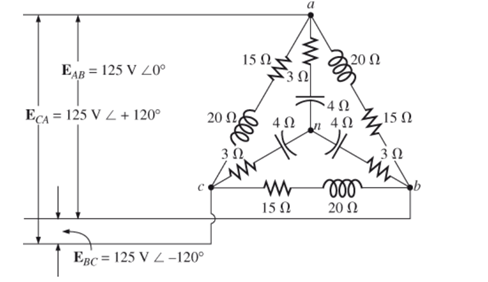
Chapter 24, Problem 43P
Find the total watts, volt-amperes reactive, volt-amperes, and Fp of the sytem in Fig. 24.52.
Expert Solution & Answer
Want to see the full answer?
Check out a sample textbook solution
Students have asked these similar questions
Find phase difference of power supply voltage and vR(wich is equal to angle of current)
In table 1
Please help me with this problem...
Question:
For the three-phase, a three-wire system of Fig. 22.52, find the magnitude of the current through each phase of the load and find the total watts, volt-amperes reactive, volt-amperes, and Fp of the load.
Three conductors of a 3-phase overhead line are arranged in a horizontal plane 6 m apart. The diameter of each conductor is 1·24 cm. Find the capacitance of each conductor to neutral per 100 km of the line.
Chapter 24 Solutions
Introductory Circuit Analysis; Laboratory Manual For Introductory Circuit Analysis Format: Kit/package/shrinkwrap
Ch. 24 - A balanced V load having a 10 resistance in each...Ch. 24 - Repeat Problem 1 if each phase impedance is...Ch. 24 - Repeat Problem 1 if each phase impedance is...Ch. 24 - The phase sequence for the Y-Y system in Fig....Ch. 24 - Repeat Problem 4 if each phase impedance are...Ch. 24 - Repeat Problem 4 if each phase impedance is...Ch. 24 - For the system in Fig. 24.43, find the magnitude...Ch. 24 - Computer the magnitude of the voltage EAB for the...Ch. 24 - For the Y-Y system in Fig. 24.45: a. Find the...Ch. 24 - For the Y-Y system of Fig. 24.46 the impedance of...
Ch. 24 - A balanced load having a 20 resistance in each...Ch. 24 - Repeat Problem 11 if each phase impedance is...Ch. 24 - Repeat Problem 11 if each phase impedance is...Ch. 24 - The phase sequence for the Y- system in Fig....Ch. 24 - Repeat Problem 14 if each phase impedance is...Ch. 24 - Repeat Problem 14 if each phase impedance are...Ch. 24 - Prob. 17PCh. 24 - For the connected load in Fig. 24.49: a. Find the...Ch. 24 - A balanced V load having a 30 resistance in each...Ch. 24 - Repeat Problem 19 if each phase impedance is...Ch. 24 - Prob. 21PCh. 24 - Prob. 22PCh. 24 - Prob. 23PCh. 24 - Repeat Problem 22 if each phase impedance is...Ch. 24 - Prob. 25PCh. 24 - Prob. 26PCh. 24 - Prob. 27PCh. 24 - The phase sequence for the - system in Fig....Ch. 24 - Repeat Problem 28 if each phase impedance is...Ch. 24 - Repeat Problem 28 if each phase impedance is...Ch. 24 - Prob. 31PCh. 24 - Prob. 32PCh. 24 - Prob. 33PCh. 24 - Find the total watts, volt-amperes reactive,...Ch. 24 - Prob. 35PCh. 24 - Find the total watts, volt-amperes reactive,...Ch. 24 - Find the total watts, volt-amperes reactive,...Ch. 24 - Prob. 38PCh. 24 - Prob. 39PCh. 24 - Find the total watts, volt-amperes reactive,...Ch. 24 - A balanced, three-phase, -connected load has a...Ch. 24 - A balanced, three-phase, Y-connected load has a...Ch. 24 - Find the total watts, volt-amperes reactive,...Ch. 24 - The Y-Y system in Fig. 24.53 has a balanced load...Ch. 24 - Prob. 45PCh. 24 - Prob. 46PCh. 24 - Repeat Problem 46 for the network in Fig. 24.47.Ch. 24 - For the three-wire system in Fig. 24.55, properly...Ch. 24 - Sketch three different ways that two wattmeters...Ch. 24 - For the Y- system in Fig. 24.56: Determine the...Ch. 24 - For the system in Fig. 24.57: Calculate the...Ch. 24 - For the three-phase, three-wire system in Fig....
Knowledge Booster


Learn more about
Need a deep-dive on the concept behind this application? Look no further. Learn more about this topic, electrical-engineering and related others by exploring similar questions and additional content below.Similar questions
- A single phase transmission line is transmitting power to a load of 1,100 KW at 11 KV and at unity power fector. If it has a total resistance of 5 Ω, what is the efficiency of the transmission line? :arrow_forwardThree conductors of a 3-phase overhead line are arranged in a horizontal plane 6 m apart. The diameter of each conductor is 1·24 cm. Find the capacitance of each conductor to neutral per 100 km of the line. [0·785 μF]arrow_forwardA three phase transmission line to line capacitive reactance value is 12 ohms. If the charging current of a line per phase is 37 A. Choose the corresponding phase voltage from the values given below. 21.07V 0.32V 444.00V 256.34Varrow_forward
- A No.10 AWG aluminum conductor carrying a load of 16A on a 220 V, single-phase circuit. Approximate the maximum distance. Use a maximum voltage drop of 3%. (Hint: the conductor has a cross-sectional area of 10, 380 cmils)arrow_forwardDerive the relationship between in case of star and delta connected load between: a). Phase voltage and line voltage b). Phase current and line currentarrow_forwardA single phase transmission line is transmitting 1,100 KW power at 11 KV and at unity power fector. If it has a total resistance of 5 Ω, what is the efficiency of the transmission line?arrow_forward
- A single phase transmission line has two parallel conductors 1.5 meters apart with 2.5cm diameter. The Loop inductance is:arrow_forwardA transmitter sends a 5W of power to a 75 ohm line. Suppose the transmitter and the line is matched but the load is not. Determine the power absorbed by the load if the coefficient of reflection is 0.75.arrow_forwarda single-phase transmission line has two parallel conductors, 1.5 meters apart. the radius of each conductor is 0.3 cm. calculate the inductance per meter of the line.arrow_forward
- For an AC source of 0.4V calculate node voltage V in rectangular and polar form?arrow_forward2.5 cm in a 200 km long transmission line. Three diameter line conductors are arranged in a horizontal formation. The line has been transposed. Find the inductance per phase and the capacitance per phase if there is a distance of 3 meters between two adjacent wires.arrow_forwardFind the phase differences between voltages and currents.arrow_forward
arrow_back_ios
SEE MORE QUESTIONS
arrow_forward_ios
Recommended textbooks for you
 Introductory Circuit Analysis (13th Edition)Electrical EngineeringISBN:9780133923605Author:Robert L. BoylestadPublisher:PEARSON
 Delmar's Standard Textbook Of ElectricityElectrical EngineeringISBN:9781337900348Author:Stephen L. HermanPublisher:Cengage Learning
 Programmable Logic ControllersElectrical EngineeringISBN:9780073373843Author:Frank D. PetruzellaPublisher:McGraw-Hill Education
 Fundamentals of Electric CircuitsElectrical EngineeringISBN:9780078028229Author:Charles K Alexander, Matthew SadikuPublisher:McGraw-Hill Education
 Electric Circuits. (11th Edition)Electrical EngineeringISBN:9780134746968Author:James W. Nilsson, Susan RiedelPublisher:PEARSON
 Engineering ElectromagneticsElectrical EngineeringISBN:9780078028151Author:Hayt, William H. (william Hart), Jr, BUCK, John A.Publisher:Mcgraw-hill Education,
Introductory Circuit Analysis (13th Edition)
Electrical Engineering
ISBN:9780133923605
Author:Robert L. Boylestad
Publisher:PEARSON
Delmar's Standard Textbook Of Electricity
Electrical Engineering
ISBN:9781337900348
Author:Stephen L. Herman
Publisher:Cengage Learning
Programmable Logic Controllers
Electrical Engineering
ISBN:9780073373843
Author:Frank D. Petruzella
Publisher:McGraw-Hill Education
Fundamentals of Electric Circuits
Electrical Engineering
ISBN:9780078028229
Author:Charles K Alexander, Matthew Sadiku
Publisher:McGraw-Hill Education
Electric Circuits. (11th Edition)
Electrical Engineering
ISBN:9780134746968
Author:James W. Nilsson, Susan Riedel
Publisher:PEARSON
Engineering Electromagnetics
Electrical Engineering
ISBN:9780078028151
Author:Hayt, William H. (william Hart), Jr, BUCK, John A.
Publisher:Mcgraw-hill Education,
Z Parameters - Impedance Parameters; Author: Electrical Engineering Authority;https://www.youtube.com/watch?v=qoD4AoNmySA;License: Standard Youtube License