
Videos
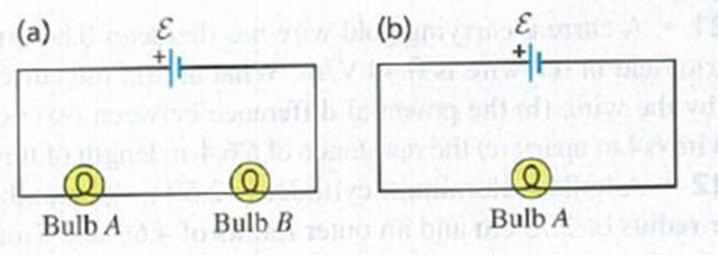
A light bulb glows because it has resistance. The brightness of a light bulb increases with the electrical power dissipated in the bulb, (a) In the circuit shown in Fig. Q25.14a, the two bulbs A and B are identical. Compared to bulb A, does bulb B glow more brightly, just as brightly, or less brightly? Explain your reasoning, (b) Bulb B is removed from the circuit and the circuit is completed as shown in Fig. Q25.l4b. Compared to the brightness of bulb A in Fig. Q25.l4a, does bulb A now glow more brightly, just as brightly, or less brightly? Explain your reasoning.
Figure Q25.14

Learn your wayIncludes step-by-step video

Chapter 25 Solutions
University Physics with Modern Physics, Volume 1 (Chs. 1-20) and Mastering Physics with Pearson eText & ValuePack Access Card (14th Edition)
Additional Science Textbook Solutions
Physics (5th Edition)
Physics for Scientists and Engineers: A Strategic Approach with Modern Physics (4th Edition)
Lecture- Tutorials for Introductory Astronomy
Physics for Scientists and Engineers with Modern Physics
Introduction to Electrodynamics
Sears And Zemansky's University Physics With Modern Physics


- The circuit shown in Figure P28.78 is set up in the laboratory to measure an unknown capacitance C in series with a resistance R = 10.0 M powered by a battery whose emf is 6.19 V. The data given in the table are the measured voltages across the capacitor as a function of lime, where t = 0 represents the instant at which the switch is thrown to position b. (a) Construct a graph of In (/v) versus I and perform a linear least-squares fit to the data, (b) From the slope of your graph, obtain a value for the time constant of the circuit and a value for the capacitance. v(V) t(s) In (/v) 6.19 0 5.56 4.87 4.93 11.1 4.34 19.4 3.72 30.8 3.09 46.6 2.47 67.3 1.83 102.2arrow_forwardThe- pair of capacitors in Figure P28.63 are fully charged by a 12.0-V battery. The battery is disconnected, and the switch is then closed. Alter 1.00 ms has elapsed, (a) how much charge remains 011 the 3.00-F capacitor? (b) How much charge remains on the 2.00-F capacitor? (c) What is the current in the resistor at this time?arrow_forwardThe switch in Figure P27.51a closes when Vc23Vand opens when Vc13V. The ideal voltmeter reads a potential difference as plotted in Figure P27.51b. What is the period T of the waveform in terms of R1, R2, and C? Figure P27.51arrow_forward
- A charge Q is placed on a capacitor of capacitance C. The capacitor is connected into the circuit shown in Figure P26.37, with an open switch, a resistor, and an initially uncharged capacitor of capacitance 3C. The switch is then closed, and the circuit comes to equilibrium. In terms of Q and C, find (a) the final potential difference between the plates of each capacitor, (b) the charge on each capacitor, and (c) the final energy stored in each capacitor. (d) Find the internal energy appearing in the resistor. Figure P26.37arrow_forwardFor the purpose of measuring the electric resistance of shoes through the body of the wearer standing on a metal ground plate, the American National Standards Institute (ANSI) specifies the circuit shown in Figure P27.14. The potential difference V across the 1.00-M resistor is measured with an ideal voltmeter. (a) Show that the resistance of the footwear is Rshoes=50.0VVV (b) In a medical test, a current through the human body should not exceed 150 A. Can the current delivered by the ANSI-specified circuit exceed 150 A? To decide, consider a person standing barefoot on the ground plate. Figure P27.14arrow_forward2o2 3052 352 552 652 2A A. The power dissipated in the 3 Ohms resistor is W. B. The total voltage is V. C. The power dissipated in the 5 Ohms resistor is W. Round all answers to whole numbers.arrow_forward
- 2. If the current in 10µF capacitor is i(t) = 5te* mA; A. Plot a graph of the current vs time. B. Find the voltage across as a function of time, plot a graph of the voltage vs time, and calculate the voltage value after t = 300ms. Assume that the capacitor is initially charged to 3mV. C. Find the energy E(t), plot a graph of the energy vs time and, determine the energy stored at time t = 1.2s.arrow_forward17.a. Four electricians are discussing voltage ratings of circuit breakers. Electrician A says that a circuitbreaker marked 120/240 V is acceptable for a circuit that doesn't exceed 220 V between any twoconductors. Electrician B says that a circuit breaker marked only 240 V wouldn't be acceptable for a circuitexceeding 220 V between any two conductors. Electrician C says that a circuit breaker marked 120/240 Vis acceptable for a circuit that exceeds 220 V between any two conductors. Electrician D says the 120/240V breaker would be acceptable for a circuit that doesn't exceed 240 V between any two conductors. Whichelectrician is correct?A. Electrician B is correct.B. Electrician C is correct.c. Electrician A is correct. 17.a. Four electricians are discussing circuit breakers used as switches. Electrician A says that circuit breakersused as switches in a 120 V circuit need to be marked SWD. Electrician B says the HID marking isn'trequired for high-intensity lighting. Electrician C…arrow_forwardA parallel plate capacitor has an air-filled gap. It is attached an EMF and charged it to charge Qo and voltage difference ΔVco. Two different experiments are done. Case A: The gap between the capacitor plates is then filled with Teflon with the capacitor still connected directly across the terminals of the EMF. Case B: The capacitor is disconnected from the EMF first before the gap in between the plates is then filled with Teflon. Which statement is true after the Teflon is inserted into the gap? 1.) In case A, ΔVc is unchanged but Q increases to keep the net E field between the plates unchanged. In case B, Q is unchanged but ΔVc decreases due to a smaller net E field between the plates. 2.) In case A, Q is unchanged but ΔVc decreases due to a smaller net E field between the plates. In case B, ΔVc is unchanged but Q increases to keep the net E field between the plates unchanged. 3.) In case A, Q is unchanged but ΔVc increases due to a larger net E field between the plates. In case…arrow_forward
- Chapter 20: Problem 7: Suppose a flashlight has 5.8 × 10² C of charge pass through it during time 0.55 h. a) What is the rate of the flashlight’s energy consumption, in watts, if it operates at a voltage of 3.00 V?arrow_forward3. The circuit in Figure P28.75 contains two resistors, R1 = 2.00 k2 and R2 = 3.00 kN, and two capacitors, C = 2.00 µF and C2 = 3.00 µF, connected to a battery with emf ɛ = 120 V. No charge is on either capacitor before switch S is closed. Determine the charges q1 and q2 on capacitors C1 and C2, respectively, after the switch is closed. (Suggestion: First reconstruct the circuit so that it becomes a simple RC circuit containing a single resistor and single capacitor in series, connected to the battery, and then deter- mine the total charge qstored in the equivalent circuit.) %3D %3D %3D R1 R2 C2 S Figure P28.75arrow_forwardQ1 Charging Capacitor At t= 0, S is closed to the A position. The capacitor begins to charge. Find the Time Rates at which: a) Charge is accumulating on the capacitor b) Energy is being stored in the capacitor c) Thermal energy is being dissipated through the resistor d) Energy is being delivered by the seat of emf. e) Evaluate for t = 1.0 s, R = 3.0 MN, C = 1.0µF, ε = 4.0 V 3 B www R 4|1|* 3 www R +q -qarrow_forward
 Physics for Scientists and Engineers with Modern ...PhysicsISBN:9781337553292Author:Raymond A. Serway, John W. JewettPublisher:Cengage Learning
 Physics for Scientists and EngineersPhysicsISBN:9781337553278Author:Raymond A. Serway, John W. JewettPublisher:Cengage Learning
 Physics for Scientists and Engineers: Foundations...PhysicsISBN:9781133939146Author:Katz, Debora M.Publisher:Cengage Learning
 Physics for Scientists and Engineers, Technology ...PhysicsISBN:9781305116399Author:Raymond A. Serway, John W. JewettPublisher:Cengage Learning
 Principles of Physics: A Calculus-Based TextPhysicsISBN:9781133104261Author:Raymond A. Serway, John W. JewettPublisher:Cengage Learning