
Concept explainers
Videos
BIO Stray voltage is a serious problem on dairy farms, often resulting from corroded wiring or poor wiring practices. These conditions can produce several volts between the ground and metal watering bowls, feed troughs, or milking equipment. Cows feel shocks that make them nervous, reducing milk output and sometimes leading to mammary gland infections. As a result, farmers can face serious financial losses. Figure 25.43 shows a typical stray-voltage situation, with the source of stray voltage modeled as a 6-V emf in series with a 1-kΩ resistance.
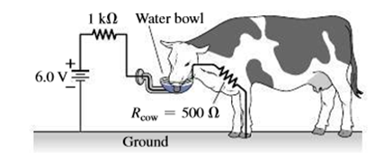
FIGURE 25.43 Stray voltage can bankrupt a dairy farm (Passage Problems 83-86)
83. The current through the 500-Ω cow will be
- a. 3 mA.
- b. 4 mA.
- c. 6 mA.
- d. 12 mA.
84. The voltage across the cow shown is
- a. 2 V.
- b. 4 V.
- c. 6 V.
- d. nearly 0 V.
85. In an effort to diagnose the problem, a farmer connects an ideal voltmeter between the water bowl and ground, with the cow absent. The voltmeter reading is
- a. 2 V.
- b. 4 V.
- c. 6 V.
- d. none of the above.
86. To explore the problem further, a farmer connects an ideal ammeter between the water bowl and ground, with the cow absent. The ammeter reading is
- a. 4 mA.
- b. 6 mA.
- c. 12 mA.
- d. infinite.
Want to see the full answer?
Check out a sample textbook solution
Chapter 25 Solutions
Mastering Physics with Pearson eText -- Standalone Access Card -- for Essential University Physics (3rd Edition)
Additional Science Textbook Solutions
University Physics Volume 1
Applied Physics (11th Edition)
Physics (5th Edition)
University Physics (14th Edition)
Conceptual Physics (12th Edition)


- Figure 21.55 shows how a bleeder resistor is used to discharge a capacitor after an electronic device is shut off allowing a person to work on the electronics with less risk of shock, (a) What is the time constant? (b) How long will it take to reduce the voltage on the capacitor to 0.250% (5% of 5%) of its full value once discharge begins? (c) If the capacitor is charged to a voltage V0through a 100-O resistance, calculate the time it takes to rise to 0.865V0(This is about two time constants.)arrow_forwardReferring to Figure CQ21.4, describe what happens to the light-bulb after the switch is closed. Assume the capacitor has a large capacitance and is initially uncharged. Also assume the light illuminates when connected directly across the battery terminals.arrow_forwardAccording to its design specification, the timer circuit delaying the closing of an elevator door is to have a capacitance of 32.0 F between two points A and B. When one circuit is being constructed, the inexpensive but durable capacitor installed between these two points is found to have capacitance 34.8 F. To meet the specification, one additional capacitor can be placed between the two points. (a) Should it be in series or in parallel with the 34.8-F capacitor? (b) What should be its capacitance? (c) What If? The next circuit comes down the assembly line with capacitance 29.8 F between A and B. To meet the specification, what additional capacitor should be installed in series or in parallel in that circuit?arrow_forward
- The circuit shown in Figure P28.78 is set up in the laboratory to measure an unknown capacitance C in series with a resistance R = 10.0 M powered by a battery whose emf is 6.19 V. The data given in the table are the measured voltages across the capacitor as a function of lime, where t = 0 represents the instant at which the switch is thrown to position b. (a) Construct a graph of In (/v) versus I and perform a linear least-squares fit to the data, (b) From the slope of your graph, obtain a value for the time constant of the circuit and a value for the capacitance. v(V) t(s) In (/v) 6.19 0 5.56 4.87 4.93 11.1 4.34 19.4 3.72 30.8 3.09 46.6 2.47 67.3 1.83 102.2arrow_forwardFigure P18.26 shows a voltage divider, a circuit used to obtain a desired voltage Vout from a source voltage . Determine the required value of R2 if = 5.00 V, Vout = 1.50 V and R1 = 1.00 103 (Hint: Use Kirchhoff's loop rule, substituting Vout = IR2, to find the current. Then solve Ohms law for R2. Figure P18.26arrow_forwardFigure P18.26 shows a voltage divider, a circuit used to obtain a desired voltage Vout from a source voltage . Determine the required value of R2 if = 5.00 V, Vout = 1.50 V and R1 = 1.00 103 (Hint: Use Kirchhoff's loop rule, substituting Vout = IR2, to find the current. Then solve Ohms law for R2. Figure P18.26arrow_forward
- Integrated Concepts If you wish to take a picture of a bullet traveling at 500 m/s, then a very brief flash of light produced by an RC discharge through a flash tube can limit blurring. Assuming 1.00 mm of motion during one RC constant is acceptable, and given that the flash is driven by a 600F capacitor, what is the resistance in the flash tube?arrow_forwardThe temperature near the center of the Sun is thought to be 15 million degrees Celsius ( 1.5107oC ) (or kelvin). Through what voltage must a singly charged ion be accelerated to have the same energy as the average kinetic energy of ions at this temperature?arrow_forwardYou have a faculty position at a community college and are m (caching a class in automotive technology. You are deep in a discussion of using jumper cables to start a car with a dead battery from a car with a fresh battery. You have drawn the circuit diagram in Figure P27.16 to explain the process. The battery on the left is the live batten- in the correctly functioning car, with emf and internal resistance RL where the L. subscript refers to live. Its terminals are connected directly across those of the dead battery, in the middle of the diagram, with emf and internal resistance RD where the D subscript refers to "dead Then, the starter in the car with the dead battery is activated by closing the ignition switch, allowing the car to start. The resistance of the starter is Rs. A student raises his hand and asks, So is the dead battery being charged while the starter is operating? How do you respond?arrow_forward
- An electronic apparatus may have large capacitors at high voltage in the power supply section, presenting a shock hazard even when the apparatus is switched off. A “bleeder resistor" is therefore placed across such a capacitor, as shown schematically in Figure 21.50, to bleed the charge from it after the apparatus is off. Why must the bleeder resistance be much greater than the effective resistance of the rest of the circuit? How does this affect the time constant for discharging the capacitor?arrow_forwardA heart defibrillator being used on a patient has an RC time constant of 10.0 ms due to the resistance of the patient and the capacitance of the defibrillator. (a) If the defibrillator has an 8.00F capacitance, what is the resistance of the path through the patient? (You may neglect the capacitance of the patient and the resistance of the defibrillator.) (b) If the initial voltage is 12.0 kV, how long does it take to decline to 6.00x10² V?arrow_forwardIf you wish to take a picture of a bullet traveling at 500 m/s, then a very brief flash of light produced by an EC discharge through a flash tube can limit blurring. Assuming 1.00 mm of motion during one EC constant is acceptable, and given that the flash is driven by a 600F capacitor, what is the resistance in the flash tube?arrow_forward
 Principles of Physics: A Calculus-Based TextPhysicsISBN:9781133104261Author:Raymond A. Serway, John W. JewettPublisher:Cengage Learning
 Physics for Scientists and Engineers, Technology ...PhysicsISBN:9781305116399Author:Raymond A. Serway, John W. JewettPublisher:Cengage Learning
 College PhysicsPhysicsISBN:9781305952300Author:Raymond A. Serway, Chris VuillePublisher:Cengage Learning
 College PhysicsPhysicsISBN:9781285737027Author:Raymond A. Serway, Chris VuillePublisher:Cengage Learning
 College PhysicsPhysicsISBN:9781938168000Author:Paul Peter Urone, Roger HinrichsPublisher:OpenStax College