College Physics- Package
3rd Edition
ISBN: 9780133913972
Author: Knight
Publisher: PEARSON
expand_more
expand_more
format_list_bulleted
Videos
Textbook Question
Chapter 26, Problem 19CQ
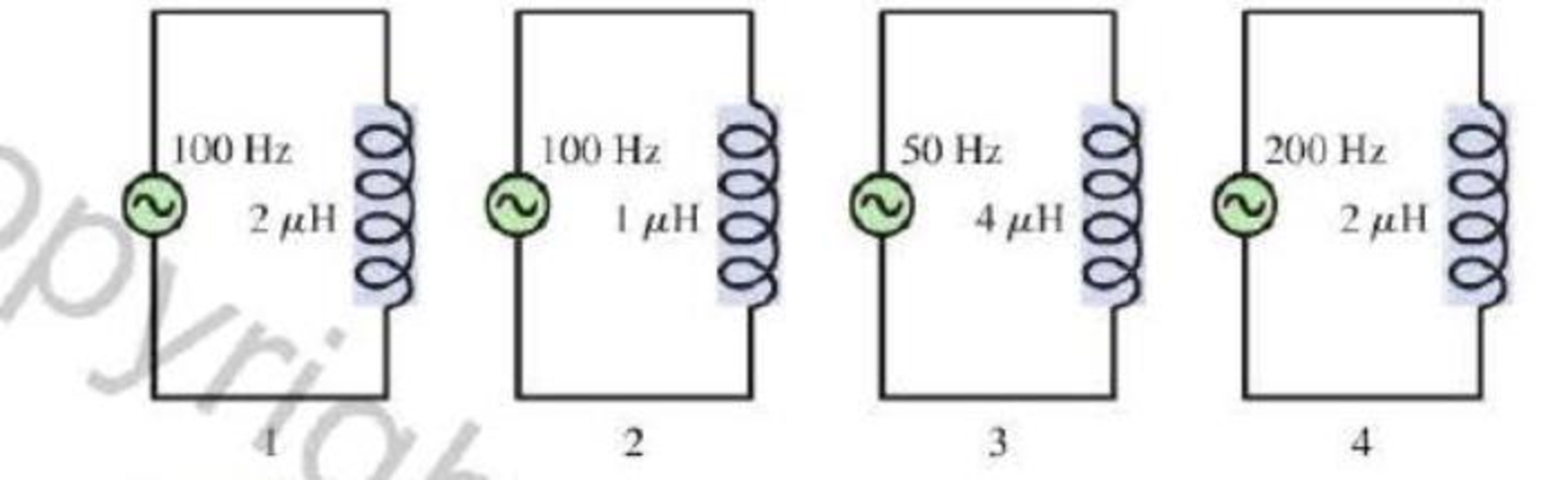
Consider the four circuits in Figure Q26.19. Rank in order, from largest to smallest, the inductive reactances (XL)1 to (XL)4. Explain.
FIGURE Q26 19
Expert Solution & Answer
Want to see the full answer?
Check out a sample textbook solution
Students have asked these similar questions
To get the maximum current, the connection should be in parallel. If you create a parallel connection with 30V DC source and three resistors with R1 = 50Ω, R2 = 75Ω, and R3 = 100Ω, how do you calculate for the total current (IT) and the current flowing in each resistor (I1, I2, I3), and the total voltage (VT) and the voltage across each resistor (V1, V2, V3)? How do you also determine the power dissipated by each resistor (P1, P2, P3) and by the whole circuit (PT)??
A circuit consists of a 40 Ω resistor and a690 mH inductor connected in series to a 14 Vbattery. What is the value of the current when thecurrent is increasing at the rate of 7 A/s?Answer in units of A
To get the minimum current, the connection should be in series. If you create a series connection with 30V DC source and three resistors with R1 = 50Ω, R2 = 75Ω, and R3 = 100Ω, how do you calculate for the total current (IT) and the current flowing in each resistor (I1, I2, I3), and the total voltage (VT) and the voltage across each resistor (V1, V2, V3)? How do you also determine the power dissipated by each resistor (P1, P2, P3) and by the whole circuit (PT)??
Chapter 26 Solutions
College Physics- Package
Ch. 26 - Identical resistors are connected to separate 12 V...Ch. 26 - Consider the three circuits in Figure Q26.2. Rank...Ch. 26 - Most battery-powered devices wont work if you put...Ch. 26 - If a lightbulb is connected to a 120 V, 60 Hz...Ch. 26 - A soldering gun contains a transformer that lowers...Ch. 26 - A 12 V DC power supply is connected to the primary...Ch. 26 - Figure Q26.7 shows three wires wrapped around an...Ch. 26 - Women usually have higher resistance of their arms...Ch. 26 - If you work out enough to visibly increase the...Ch. 26 - The peak current through a capacitor is 2.0 A....
Ch. 26 - Consider the four circuits in Figure Q26.14. Rank...Ch. 26 - Prob. 15CQCh. 26 - Prob. 16CQCh. 26 - Figure Q26.17 shows two inductors and the...Ch. 26 - The peak current passing through an inductor is...Ch. 26 - Consider the four circuits in Figure Q26.19. Rank...Ch. 26 - The tuning circuit in a radio uses an RLC circuit....Ch. 26 - The resonance frequency of a driven RLC circuit is...Ch. 26 - Consider the four circuits in Figure Q26.22. They...Ch. 26 - Prob. 23MCQCh. 26 - An inductor is connected to an AC generator. As...Ch. 26 - A capacitor is connected to an AC generator. As...Ch. 26 - An AC source is connected to a series combination...Ch. 26 - An AC source is connected to a series combination...Ch. 26 - The circuit shown in Figure Q26.28 has a resonance...Ch. 26 - At resonance, a driven RLC circuit has VC = 5.0 V,...Ch. 26 - A driven RLC circuit has VC = 5.0V, VR = 7.0 V,...Ch. 26 - A 200 resistor is connected to an AC source with...Ch. 26 - Figure P26.2 shows voltage and current graphs for...Ch. 26 - A resistor dissipates 2.00 W when the rms voltage...Ch. 26 - The heating element of a hair dryer dissipates...Ch. 26 - A toaster oven is rated at 1600 W for operation at...Ch. 26 - A small electric space heater uses a wire that has...Ch. 26 - A generator produces 40 MW of power and sends it...Ch. 26 - Soles of hoots that are designed to protect...Ch. 26 - The primary coil of a transformer is connected to...Ch. 26 - A soldering iron uses an electric current in a...Ch. 26 - A power pack charging a cell phone battery has an...Ch. 26 - A neon sign transformer has a 450 W AC output with...Ch. 26 - Prob. 13PCh. 26 - A science hobbyist has purchased a surplus...Ch. 26 - A generator produces 250 kW of electric power at...Ch. 26 - In an old house, the wires leading lo a 120 V...Ch. 26 - A typical American family uses 1000 kWh of...Ch. 26 - The wiring in the wall of your house to and from...Ch. 26 - The following appliances are connected to a single...Ch. 26 - Your refrigerator uses 220 W when the compressor...Ch. 26 - A 60 W (120 V) night light is turned on for an...Ch. 26 - Suppose you leave a 110 W television and two 100 W...Ch. 26 - The manufacturer of an electric table saw claims...Ch. 26 - John is changing a lightbulb in a lamp, Its a warm...Ch. 26 - In some countries AC outlets near bathtubs are...Ch. 26 - If you touch the terminal of a battery, the small...Ch. 26 - A person standing barefoot on the ground 20 m from...Ch. 26 - Electrodes used to make electrical measurements of...Ch. 26 - A fisherman has netted a torpedo ray. As he picks...Ch. 26 - Problems 30 and 31 concern a high-voltage...Ch. 26 - Problems 30 and 31 concern a high-voltage...Ch. 26 - A 0.30 F capacitor is connected across an AC...Ch. 26 - A 20 F capacitor is connected across an AC...Ch. 26 - The peak current through a capacitor is 10.0 mA....Ch. 26 - A 20 nF capacitor is connected across an AC...Ch. 26 - A capacitor is connected to a 15 kHz oscillator...Ch. 26 - The peak current through a capacitor is 8.0 mA...Ch. 26 - Prob. 38PCh. 26 - A 20 mH inductor is connected across an AC...Ch. 26 - The peak current through an inductor is 10.0 mA....Ch. 26 - A 500 H inductor is connected across an AC...Ch. 26 - An inductor is connected to a 15 kHz oscillator...Ch. 26 - The peak current through an inductor is 12.5 mA...Ch. 26 - A 2.0 mH inductor is connected in parallel with a...Ch. 26 - An FM radio station broadcasts at a frequency of...Ch. 26 - The inductor in the RLC tuning circuit of an AM...Ch. 26 - At what frequency f do a 1.0 F capacitor and a 1.0...Ch. 26 - What capacitor in series with a 100 resistor and...Ch. 26 - What inductor in series with a 100 resistor and a...Ch. 26 - A series RLC circuit has a 200 kHz resonance...Ch. 26 - An RLC circuit with a 10 F capacitor is connected...Ch. 26 - A series KLC circuit consists of a 280 resistor,...Ch. 26 - Electric outlets in England are 230 V. Alice...Ch. 26 - The voltage-to-current ratio in the primary coil...Ch. 26 - A 15-km-long, 230 kV aluminum transmission line...Ch. 26 - The voltage across a 60 F capacitor is described...Ch. 26 - Prob. 57GPCh. 26 - An electronics hobbyist is building a radio set to...Ch. 26 - For the circuit of Figure P26.59 a. What is the...Ch. 26 - For the circuit of Figure P26.60 a. What is the...Ch. 26 - An RLC circuit consists of a 48 resistor, a 200 F...Ch. 26 - Cell Membrane Resistance The capacitance of...Ch. 26 - Cell Membrane Resistance The capacitance of...Ch. 26 - Cell Membrane Resistance The capacitance of...Ch. 26 - Cell Membrane Resistance The capacitance of...Ch. 26 - Halogen Bulbs Halogen bulbs have some differences...Ch. 26 - Halogen Bulbs Halogen bulbs have some differences...Ch. 26 - Halogen Bulbs Halogen bulbs have some differences...Ch. 26 - Halogen Bulbs Halogen bulbs have some differences...
Additional Science Textbook Solutions
Find more solutions based on key concepts
A 15-F capacitor carries 1.4 A rms. Whats its minimum safe voltage rating if the frequency is (a) 60 Hz and (b)...
Essential University Physics (3rd Edition)
* When does the kinetic energy of a car change more: when the car accelerates from 0 to 10 m/s or from 30 m/s t...
College Physics
3. What is free-fall, and why does it make you weightless? Briefly describe why astronauts are weightless in th...
The Cosmic Perspective (8th Edition)
Q6.10 Does a car’s kinetic energy change more when the car speeds up from 10 to 15 m/s or from 15 to 20 m/s? Ex...
University Physics with Modern Physics (14th Edition)
Choose the best answer to each of the following. Explain your reasoning. Which of these star clusters is younge...
The Cosmic Perspective Fundamentals (2nd Edition)
68. A student that you’re tutoring says that the terms wave speed and wave frequency refer to the same thing. W...
Conceptual Physical Science (6th Edition)
Knowledge Booster


Learn more about
Need a deep-dive on the concept behind this application? Look no further. Learn more about this topic, physics and related others by exploring similar questions and additional content below.Similar questions
- Figure P29.84 shows a circuit that consists of two identical emf devices. If R1 = R2 = R and the switch is closed, find an expression (in terms of R and ) for the current I that is in the branch from point a to b.arrow_forwardIn Figure OQ32.4, the switch is left in position a for a long lime interval and is then quickly thrown to position b. Rank the magnitudes of the voltages across the Four circuit elements a short time thereafter from the largest to the smallest.arrow_forwardIn Figure 33.9A (page 1052), the switch is closed at a at t = 0. Find an expression for the power dissipated by the resistor as a function of time, and sketch your result. Is the power lost greater as soon as the switch is closed or a long time after it has been closed? Does your answer make sense?arrow_forward
- In an RLC circuit, L = 5.0 mH, C = 6.0μF, and R = 200 Ω. (a) Is the circuit underdamped, critically damped, or overdamped? (b) If the circuit starts oscillating with a charge of 3.0 × 10⁻³ C on the capacitor, how much energy has been dissipated in the resistor by the time the oscillations cease?arrow_forwardThe capacitor in 23.55(a) is designed to filter lowfrequency signals, impeding their transmission between circuits. (a) What capacitance is needed to produce a 100 kΩ reactance at a frequency of 120 Hz? (b) What would its reactance be at 1.00 MHz? (c) Discuss theimplications of your answers to (a) and (b).arrow_forward1.a. Which article of the National Electrical Code covers radio and television equipment?A. 770B. 517C. 810D. 7051.b. All _______-ampere receptacles for sensitive electronic equipment must be ground-fault circuitinterrupter protected.A. 10- and 30B. 10- and 15C. 20- and 30D. 15- and 20arrow_forward
- What is the approximate phase angle in a series RLC circuit when VC = 117 V, VR = 14.5 V, and VL = 3.3 V? A. –45.0 degrees B. –82.7 degrees C. –90.0 degrees D. –172.7 degreesarrow_forwardConsider a series RLC circuit for which R = 150 Ω, L = 20.0 mH, ΔVrms = 20.0 V, and ω = 5 000 s-1. Determine the value of the capacitance for which the current is a maximum.arrow_forwardA capacitor and a resistor are connected in series across anAC generator, as shown in Figure CQ21.17. After the switchis closed, which of the following statements is true? (a) Thevoltage across the capacitor lags the current by 90°. (b) Thevoltage across the resistor is out of phase with the current. (c) The voltage across the capacitor leads the current by 90°.(d) The current decreases as the frequency of the generatoris increased, but its peak voltage remains the same. (e) Noneof thesearrow_forward
- The voltage across a 70 μF�F capacitor is described by the equation vC=(18V)cos(200t)�C=(18V)cos(200�), where t� is in seconds. Part A What is the voltage across the capacitor at t� = 0.016 ss ? Express your answer with the appropriate units. Part B What is the capacitive reactance? Express your answer with the appropriate units. Part C What is the peak current? Express your answer with the appropriate units.arrow_forwardIn a purely inductive AC circuit as shown in Figure P21.15, Vmax = 100. V. (a) The maximum current is 7.50 A at 50.0 Hz. Calculate the inductance L. (b) At what angular frequency is the maximum current 2.50A? Figure p21.15arrow_forwardIn a purely inductive AC circuit as shown in Figure P21.15, Vmax = 100. V. (a) The maximum current is 7.50 A at 50.0 Hz. Calculate the inductance L. (b) At what angular frequency is the maximum current 2.50A? Figure p21.15arrow_forward
arrow_back_ios
SEE MORE QUESTIONS
arrow_forward_ios
Recommended textbooks for you
 College PhysicsPhysicsISBN:9781305952300Author:Raymond A. Serway, Chris VuillePublisher:Cengage Learning
 College PhysicsPhysicsISBN:9781285737027Author:Raymond A. Serway, Chris VuillePublisher:Cengage Learning
 Physics for Scientists and EngineersPhysicsISBN:9781337553278Author:Raymond A. Serway, John W. JewettPublisher:Cengage Learning
 Physics for Scientists and Engineers with Modern ...PhysicsISBN:9781337553292Author:Raymond A. Serway, John W. JewettPublisher:Cengage Learning
 Physics for Scientists and Engineers: Foundations...PhysicsISBN:9781133939146Author:Katz, Debora M.Publisher:Cengage Learning
College Physics
Physics
ISBN:9781305952300
Author:Raymond A. Serway, Chris Vuille
Publisher:Cengage Learning
College Physics
Physics
ISBN:9781285737027
Author:Raymond A. Serway, Chris Vuille
Publisher:Cengage Learning
Physics for Scientists and Engineers
Physics
ISBN:9781337553278
Author:Raymond A. Serway, John W. Jewett
Publisher:Cengage Learning
Physics for Scientists and Engineers with Modern ...
Physics
ISBN:9781337553292
Author:Raymond A. Serway, John W. Jewett
Publisher:Cengage Learning
Physics for Scientists and Engineers: Foundations...
Physics
ISBN:9781133939146
Author:Katz, Debora M.
Publisher:Cengage Learning
What is Electromagnetic Induction? | Faraday's Laws and Lenz Law | iKen | iKen Edu | iKen App; Author: Iken Edu;https://www.youtube.com/watch?v=3HyORmBip-w;License: Standard YouTube License, CC-BY