
Concept explainers
Videos
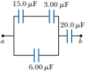
Four capacitors are connected as shown in Figure P25.11. (a) Find the equivalent capacitance between points a and b. (b) Calculate the charge on each capacitor, taking ΔVab = 15.0 V.
Figure P25.11
(a)
Answer to Problem 26.23P
Explanation of Solution
Given information:
The four capacitors are connected in figure given below:
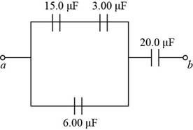
Figure (1)
Explanation:
The capacitors
Formula to calculate the equivalent capacitance when they are connected in series.
Here,
Substitute
The capacitors
Formula to calculate the equivalent capacitance when they are connected in parallel.
Here,
Substitute
The capacitors
Formula to calculate the equivalent capacitance when they are connected in series.
Here,
Substitute
Thus, the equivalent capacitance between
Conclusion:
Therefore, the equivalent capacitance between
(b)
Answer to Problem 26.23P
Explanation of Solution
Given information:
The voltage across

Explanation:
Formula to calculate the total charge in the circuit.
Here,
Substitute
Thus, the total charge in the circuit and the charge through
Formula to calculate the potential drop across
Substitute
Thus, the potential drop across
Formula to calculate the potential drop across
Substitute
Thus, the potential drop across
Formula to calculate the charge across
Substitute
Thus, the charge across
The charge across capacitors
Calculate the charge for the capacitor
Substitute
Thus, the charge across capacitors
Conclusion:
Therefore, the charge across capacitors
Want to see more full solutions like this?
Chapter 26 Solutions
EBK PHYSICS:F/SCI.+ENGRS.,TECH.UPDATED


- Figure P27.75 shows four capacitors with CA = 4.00 F, CB = 8.00 F. CC = 6.00 F. and CD = 5.00 F connected across points a and b, which have potential difference Vab = 12.0 V. a. What is the equivalent capacitance of the four capacitors? b. What is the charge on each of the four capacitors?arrow_forwardFour capacitors are connected as shown in Figure P25.11. (a) Find the equivalent capacitance between points a and b. (b) Calculate the charge on each capacitor, taking Vab = 15.0 V. Figure P25.11arrow_forwardGiven the arrangement of capacitors in Figure P27.23, find an expression for the equivalent capacitance between points a and b. Figure P27.23 Problems 23 and 24.arrow_forward
- Find the equivalent capacitance between points a and b in the combination of capacitors shown in Figure P25.13. Figure P25.13arrow_forwardIn Figure P27.7, capacitor 1 (C1 = 20.0 F) initially has a potential difference of 50.0 V and capacitor 2 (C2 = 5.00 F) has none. The switches are then closed simultaneously. a. Find the final charge on each capacitor after a long time has passed. b. Calculate the percentage of the initial stored energy that was lost when the switches were closed. FIGURE P27.7arrow_forwardFind (a) the equivalent capacitance of the capacitors in Figure P26.26, (b) the charge on each capacitor, and (c) the potential difference across each capacitor.arrow_forward
- A spherical capacitor consists of a spherical conducting shell of radius b and charge 2Q that is concentric with a smaller conducting sphere of radius a and charge +Q (Fig. P20.36). (a) Show that its capacitance is C=abke(ba) (b) Show that as b approaches infinity, the capacitance approaches the value a/ke = 40a. Figure P20.36arrow_forwardA spherical capacitor is formed from two concentric spherical conducting spheres separated by vacuum. Tire inner sphere has radius 12.5 cm and the outer sphere has radius 14.8 cm. A potential difference of 120 V is applied to the capacitor, (a) What is the capacitance of the capacitor? tb) What is the magnitude of the electrical field at r = 12.6 cm, just outside the inner sphere? (c) What is the magnitude of the electrical field at r = 14.7 cm, just inside the outer sphere? (d) For a parallel-plate capacitor the electrical field is uniform in the region between the plates, except near the edges of the plates. Is this also true for a spherical capacitor?arrow_forward(a) Find the equivalent capacitance between points a and b for the group of capacitors connected as shown in Figure P20.44. Take C1 = 5.00 F, C2 = 10.0 F, and C3 = 2.00 F. (b) What charge is stored on C3 if the potential difference between points a and b is 60.0 V? Figure P20.44arrow_forward
- (a) Find the equivalent capacitance between points a and b for the group of capacitors connected as shown in Figure P25.12 (page 686). Take C1 = 5.00 F, C2 = 10.0 F, and C3 = 2.00 F. (b) What charge is stored on C3 if the potential difference between points a and b is 60.0 V? Figure P25.12arrow_forwardFour capacitors are connected as shown in Figure P20.45. (a) Find the equivalent capacitance between points a and b. (b) Calculate the charge on each capacitor, taking Vab = 15.0 V. Figure P20.45arrow_forwardA parallel-plate capacitor has square plates of side s = 2.50 cm and plate separation d = 2.50 mm. The capacitor is charged by a battery to a charge Q = 4.00 C, after which the battery is disconnected. A porcelain dielectric ( = 6.5) is then inserted a distance y = 1.00 cm into the capacitor (Fig. P27.88). Hint: Consider the system as two capacitors connected in parallel. a. What is the effective capacitance of this capacitor? b. How much energy is stored in the capacitor? c. What are the magnitude and direction of the force exerted on the dielectric by the plates of the capacitor? Figure P27.88arrow_forward
 Physics for Scientists and Engineers with Modern ...PhysicsISBN:9781337553292Author:Raymond A. Serway, John W. JewettPublisher:Cengage Learning
 Physics for Scientists and EngineersPhysicsISBN:9781337553278Author:Raymond A. Serway, John W. JewettPublisher:Cengage Learning
 Principles of Physics: A Calculus-Based TextPhysicsISBN:9781133104261Author:Raymond A. Serway, John W. JewettPublisher:Cengage Learning
 College PhysicsPhysicsISBN:9781305952300Author:Raymond A. Serway, Chris VuillePublisher:Cengage Learning
 College PhysicsPhysicsISBN:9781285737027Author:Raymond A. Serway, Chris VuillePublisher:Cengage Learning
 Physics for Scientists and Engineers: Foundations...PhysicsISBN:9781133939146Author:Katz, Debora M.Publisher:Cengage Learning