
Mastering Physics with Pearson eText -- Standalone Access Card -- for University Physics with Modern Physics (14th Edition)
14th Edition
ISBN: 9780133978216
Author: Hugh D. Young, Roger A. Freedman
Publisher: PEARSON
expand_more
expand_more
format_list_bulleted
Videos
Textbook Question
Chapter 26, Problem 26.43E
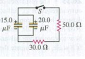
CP In the circuit shown in Fig. E26.43 both capacitors are initially charged to 45.0 V. (a) How long after closing the switch S will the potential across each capacitor be reduced to 10.0 V, and (b) what will be the current at that time?
Figure E26.43
Expert Solution & Answer

Learn your wayIncludes step-by-step video

schedule03:47
Students have asked these similar questions
A 14.7 µF capacitor is charged by a 27.0 V battery through a resistance R. The capacitor reaches a potential difference of 4.00 V at
time 3.00 s after charging begins. Find R.
kQ
A2.0 µF capacitor is charged to 12 Vand then discharged througha 4.0 M2 resistor. How long will it take for the voltage across the capacitor to drop to 3.0v?
Hint: The unknown time is in "log jail". Break it out with the inverse function of the exponential.
O 8.0 s
O 24 s
O 11 s
O 22 s
A 13.0 µF capacitor is charged by a 14.0 V battery through a resistance R.
The capacitor reaches a potential difference of 4.00 V at a time 3.00 s after
charging begins. Find R.
Chapter 26 Solutions
Mastering Physics with Pearson eText -- Standalone Access Card -- for University Physics with Modern Physics (14th Edition)
Ch. 26.1 - Suppose all three of the resistors shown in Fig....Ch. 26.2 - Subtract Eq. (1) from Eq. (2) in Example 26.6. To...Ch. 26.3 - You want to measure the current through and the...Ch. 26.4 - The energy stored in a capacitor is equal to...Ch. 26.5 - To prevent the circuit breaker in Example 26.14...Ch. 26 - In which 120-V light bulb does the filament have...Ch. 26 - Two 120-V light bulbs, one 25-W and one 200-W,...Ch. 26 - You connect a number of identical light bulbs to a...Ch. 26 - In the circuit shown in Fig. Q26.4, three...Ch. 26 - If two resistors R1 and R2 (R2 R1) are connected...
Ch. 26 - If two resistors R1 and R2 (R2 R1) are connected...Ch. 26 - A battery with no internal resistance is connected...Ch. 26 - A resistor consists of three identical metal...Ch. 26 - A light bulb is connected in the circuit shown in...Ch. 26 - A real battery, having nonnegligible internal...Ch. 26 - If the battery in Discussion Question Q26.10 is...Ch. 26 - Consider the circuit shown in Fig. Q26.12. What...Ch. 26 - Is it possible to connect resistors together in a...Ch. 26 - The battery in the circuit shown in Fig. Q26.14...Ch. 26 - In a two-cell flashlight, the batteries are...Ch. 26 - Identical light bulbs A, B, and C are connected as...Ch. 26 - The emf of a flashlight battery is roughly...Ch. 26 - Will the capacitors in the circuits shown in Fig....Ch. 26 - Verify that the time constant RC has units of...Ch. 26 - For very large resistances it is easy to construct...Ch. 26 - When a capacitor, battery, and resistor are...Ch. 26 - A uniform wire of resistance R is cut into three...Ch. 26 - A machine part has a resistor X protruding from an...Ch. 26 - A resistor with R1 = 25.0 is connected to a...Ch. 26 - A 42- resistor and a 20- resistor are connected in...Ch. 26 - A triangular array of resistors is shown in Fig....Ch. 26 - For the circuit shown in Fig. E26.6 both meters...Ch. 26 - For the circuit shown in Fig. E26.7 find the...Ch. 26 - Three resistors having resistances of 1.60 , 2.40...Ch. 26 - Now the three resistors of Exercise 26.8 are...Ch. 26 - Power Rating of a Resistor. The power rating of a...Ch. 26 - In Fig. E26.11, R1, = 3.00 , R2 = 6.00 , and R3=...Ch. 26 - In Fig. E26.11 the battery has emf 35.0 V and...Ch. 26 - Compute the equivalent resistance of the network...Ch. 26 - Compute the equivalent resistance of the network...Ch. 26 - In the circuit of Fig. E26.15, each resistor...Ch. 26 - Consider the circuit shown in Fig. E26.16. The...Ch. 26 - In the circuit shown in Fig. E26.17, the voltage...Ch. 26 - In the circuit shown in Fig. E26.18, = 36.0 V,...Ch. 26 - CP In the circuit in Fig. E26.19, a 20.0- resistor...Ch. 26 - In the circuit shown in Fig. E26.20, the rate at...Ch. 26 - Light Bulbs in Series and in Parallel. Two light...Ch. 26 - Light Bulbs in Series. A 60-W, 120-V light bulb...Ch. 26 - In the circuit shown in Fig. E26.23, ammeter A1...Ch. 26 - The batteries shown in the circuit in Fig. E26.24...Ch. 26 - In the circuit shown in Fig. E26.25 find (a) the...Ch. 26 - Find the emfs 1 and 2 in the circuit of Fig....Ch. 26 - In the circuit shown in Fig. E26.27, find (a) the...Ch. 26 - In the circuit shown in Fig. E26.28, find (a) the...Ch. 26 - The 10.00-V battery in Fig. E26.28 is removed from...Ch. 26 - The 5.00-V battery in Fig. E26.28 is removed from...Ch. 26 - In the circuit shown in Fig. E26.31 the batteries...Ch. 26 - In the circuit shown in Fig. E26.32 both batteries...Ch. 26 - In the circuit shown in Fig. E26.33 all meters are...Ch. 26 - In the circuit shown in Fig. E26.34, the 6.0-...Ch. 26 - The resistance of a galvanometer coil is 25.0 ,...Ch. 26 - The resistance of the coil of a pivoted coil...Ch. 26 - A circuit consists of a series combination of...Ch. 26 - A galvanometer having a resistance of 25.0 has a...Ch. 26 - A capacitor is charged to a potential of 12.0 V...Ch. 26 - You connect a battery, resistor, and capacitor as...Ch. 26 - A 4.60-F capacitor that is initially uncharged is...Ch. 26 - You connect a battery, resistor, and capacitor as...Ch. 26 - CP In the circuit shown in Fig. E26.43 both...Ch. 26 - A 12.4-F capacitor is connected through a 0.895-M...Ch. 26 - An emf source with = 120 V, a resistor with R =...Ch. 26 - A resistor and a capacitor are connected in series...Ch. 26 - CP In the circuit shown in Fig. E26.47 each...Ch. 26 - A 1.50-F capacitor is charging through a 12.0-...Ch. 26 - In the circuit in Fig. E26.49 the capacitors are...Ch. 26 - A 12.0-F capacitor is charged to a potential of...Ch. 26 - In the circuit shown in Fig. E26.51, C = 5.90 F, ...Ch. 26 - Prob. 26.52ECh. 26 - A 1500-W electric beater is plugged into the...Ch. 26 - In Fig. P26.54, the battery has negligible...Ch. 26 - The two identical light bulbs in Example 26.2...Ch. 26 - Each of the three resistors in Fig. P26.56 has a...Ch. 26 - (a) Find the potential of point a with respect to...Ch. 26 - CP For the circuit shown in Fig. P26.58 a 20.0-...Ch. 26 - Calculate the three currents I1, I2, and I3...Ch. 26 - What must the emf in Fig. P26.60 be in order for...Ch. 26 - Find the current through each of the three...Ch. 26 - (a) Find the current through the battery and each...Ch. 26 - Consider the circuit shown in Fig. P26.63. (a)...Ch. 26 - In the circuit shown in Fig. P26.64, = 24.0 V,...Ch. 26 - In the circuit shown in Fig. P26.65, the current...Ch. 26 - In the circuit shown in Fig. P26.66 all the...Ch. 26 - Figure P26.67 employs a convention often used in...Ch. 26 - Three identical resistors are connected in series....Ch. 26 - A resistor R1 consumes electrical power P1 when...Ch. 26 - The capacitor in Fig. F26.70 is initially...Ch. 26 - A 2.00-F capacitor that is initially uncharged is...Ch. 26 - A 6.00-F capacitor that is initially uncharged is...Ch. 26 - Point a in Fig. P26.73 is maintained at a constant...Ch. 26 - The Wheatstone Bridge. The circuit shown in Fig....Ch. 26 - (See Problem 26.67.) (a) What is the potential of...Ch. 26 - A 2.36-F capacitor that is initially uncharged is...Ch. 26 - A 224- resistor and a 589- resistor are connected...Ch. 26 - A resistor with R = 850 is connected to the...Ch. 26 - A capacitor that is initially uncharged is...Ch. 26 - DATA You set up the circuit shown in Fig. 26.22a,...Ch. 26 - DATA You set up the circuit shown in Fig. 26.20....Ch. 26 - DATA The electronics supply company where you work...Ch. 26 - An Infinite Network. As shown in Fig. P26.83, a...Ch. 26 - Suppose a resistor R lies along each edge of a...Ch. 26 - BIO Attenuator Chains and Axons. The infinite...Ch. 26 - Assume that a typical open ion channel spanning an...Ch. 26 - In a simple model of an axon conducting a nerve...Ch. 26 - Cell membranes across a wide variety of organisms...
Additional Science Textbook Solutions
Find more solutions based on key concepts
Fill in each blank with the most reasonable metric unit (km, m, cm, or mm).
23. A jet plane usually cruises at ...
Applied Physics (11th Edition)
Consider the change in velocity vector between two points on the velocity diagram that are not consecutive. e.g...
Tutorials in Introductory Physics
Wildlife biologists fire 20-g rubber bullets to stop a rhinoceros charging at 0.81 m/s. The bullets strike the ...
Essential University Physics (3rd Edition)
The setup depicted in Figure 4.6 is used in a diffraction experiment using X-rays of 0.26 nm wavelength. Constr...
Modern Physics
Use the following illustration to answer Exercises 49-51.
50. There is an excess of at least one of the reacta...
Conceptual Physical Science (6th Edition)
Explain all answers clearly, using complete sentence and proper essay structure if needed. An asterisk (*) desi...
Cosmic Perspective Fundamentals
Knowledge Booster


Learn more about
Need a deep-dive on the concept behind this application? Look no further. Learn more about this topic, physics and related others by exploring similar questions and additional content below.Similar questions
- The- pair of capacitors in Figure P28.63 are fully charged by a 12.0-V battery. The battery is disconnected, and the switch is then closed. Alter 1.00 ms has elapsed, (a) how much charge remains 011 the 3.00-F capacitor? (b) How much charge remains on the 2.00-F capacitor? (c) What is the current in the resistor at this time?arrow_forwardAn oceanographer is studying how the ion concentration in seawater depends on depth. She makes a measurement by lowering into the water a pair of concentric metallic cylinders (Fig. P21.66) at the end of a cable and taking data to determine the resistance between these electrodes as a function of depth. The water between the two cylinders forms a cylindrical shell of inner radius ra, outer radius rb, and length L much larger than rb. The scientist applies a potential difference V between the inner and outer surfaces, producing an outward radial current I. Let represent the resistivity of the water. (a) Find the resistance of the water between the cylinders in terms of L, , ra, an rb. (b) Express the resistivity of the water in terms of the measured quantities L, ra, rb, V, and I. Figure P21.66arrow_forwardConsider the circuit shown in Figure P26.24, where C1, = 6.00 F, C2 = 3.00 F. and V = 20.0 V. Capacitor C1 is first charged by closing switch S1. Switch S1 is then opened, and the charged capacitor is connected to the uncharged capacitor by closing Calculate (a) the initial charge acquired by C, and (b) the final charge on each capacitor.arrow_forward
- The circuit in Figure P21.59 has been connected for a long time. (a) What is the potential difference across the capacitor? (b) If the battery is disconnected from the circuit, over what time interval does the capacitor discharge to one-tenth its initial voltage?arrow_forwardA heart pacemaker fires exactly 73times a minute. Each time it fires, a 35.0 nF capacitor is charged by a battery in series with a resistor to 0.682 of its full voltage. What is the value of the resistance ? ?arrow_forwardIn the circuit shown both capacitors are initially charged to 45.0 V. (a) How long after closing the switch S will the potential across each capacitor be reduced to 10.0 V, and (b) what will be the current at that time? 15.0 20.0 50.0 N µF µF 30.0 Narrow_forward
- What is the time constant for the discharge of the capacitors in the circuit shown in the figure? if the 2.00 uf capacitor initially has a potential difference of 10v across its plates. how much charge remains after the switch has been closed for a time equal to half the time constant?arrow_forwardA capacitor with capacitance C = 5 μF is charged to a voltage V = 10V. It is then discharged through a resistor R = 2 MΩ. At what time after the start of the discharge process has the voltage across the capacitor fallen to 1V? Select one: a. 230 msecs b. 23 secs c. 10 secs d. 100 msecsarrow_forwardIn the figure the ideal batteries have emfs E1 = 4,89 V and E2 = 10.2 V, the resistances are each 2.41 Q, and the potential is defined to be zero at the grounded point of the circuit. What are potentials (a)V1 and (b)V2 at the indicated points? R. R3 Units (a) Number Units (b) Numberarrow_forward
- A 200 micro Farad capacitor is charged up by connecting it in series with a 10,000 ohm resistor and a 25 V battery. What is the maximum amount of charge that can be stored on the capacitor in mC?arrow_forwardA 1.40E-5F capacitor is charged by a 10.0V battery through a resistance R. The capacitor reaches a potential difference of 4.43V at a time 2.08s after charging begins. Find R.arrow_forwardThe circuit in Figure P27.41 contains two resistors, R1 = 2.00 kΩ and R2 = 3.00 kΩ, and two capacitors, C1 = 2.00 μF and C2 = 3.00 μF, connected to a battery with emf ε = 120 V. If there are no charges on the capacitors before switch S is closed, determine the charges on capacitors (a) C1 and (b) C2 as functions of time, after the switch is closed.arrow_forward
arrow_back_ios
SEE MORE QUESTIONS
arrow_forward_ios
Recommended textbooks for you
 Physics for Scientists and Engineers, Technology ...PhysicsISBN:9781305116399Author:Raymond A. Serway, John W. JewettPublisher:Cengage Learning
 Principles of Physics: A Calculus-Based TextPhysicsISBN:9781133104261Author:Raymond A. Serway, John W. JewettPublisher:Cengage Learning
 Physics for Scientists and EngineersPhysicsISBN:9781337553278Author:Raymond A. Serway, John W. JewettPublisher:Cengage Learning
 Physics for Scientists and Engineers with Modern ...PhysicsISBN:9781337553292Author:Raymond A. Serway, John W. JewettPublisher:Cengage Learning
 Physics for Scientists and Engineers: Foundations...PhysicsISBN:9781133939146Author:Katz, Debora M.Publisher:Cengage Learning
Physics for Scientists and Engineers, Technology ...
Physics
ISBN:9781305116399
Author:Raymond A. Serway, John W. Jewett
Publisher:Cengage Learning
Principles of Physics: A Calculus-Based Text
Physics
ISBN:9781133104261
Author:Raymond A. Serway, John W. Jewett
Publisher:Cengage Learning
Physics for Scientists and Engineers
Physics
ISBN:9781337553278
Author:Raymond A. Serway, John W. Jewett
Publisher:Cengage Learning
Physics for Scientists and Engineers with Modern ...
Physics
ISBN:9781337553292
Author:Raymond A. Serway, John W. Jewett
Publisher:Cengage Learning
Physics for Scientists and Engineers: Foundations...
Physics
ISBN:9781133939146
Author:Katz, Debora M.
Publisher:Cengage Learning
DC Series circuits explained - The basics working principle; Author: The Engineering Mindset;https://www.youtube.com/watch?v=VV6tZ3Aqfuc;License: Standard YouTube License, CC-BY