
Concept explainers
Videos
For (he system of four capacitors shown in Figure P26.19. find (a) the total energy stored in the system and (b) the energy stored by each capacitor, (c) (Compare the sum of the answers in part (b) with your result to part (a) and explain your observation.
(a)
The energy stored in the system.
Answer to Problem 26.56AP
The energy stored in the system is
Explanation of Solution
Given info: The electric potential in the system is
The Figure of the circuit diagram is shown below.
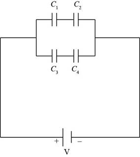
Figure (1)
Since, the capacitors
Here,
Substitute
Thus, the equivalent capacitance of the first row is
Since, the capacitors
Here,
Substitute
Thus, the equivalent capacitance of the second row is
Since, the first and second rows are in parallel to each other. So, the equivalent capacitance of the system is,
Here,
Substitute
Thus, the equivalent capacitance of the system is
Formula to calculate the energy stored in the system is,
Here,
Substitute
Conclusion:
Therefore, the energy stored in the system is
(b)
The energy stored by each capacitor.
Answer to Problem 26.56AP
The energy stored in capacitors
Explanation of Solution
Given info: The electric potential in the system is
Since, the electric potential through each capacitor is same.
Formula to calculate the charge on the first row of capacitor is,
Here,
Substitute
Thus, the charge on the first row of capacitor is
Formula to calculate the energy stored is,
Here,
The energy stored in capacitor
Here,
Substitute
Thus, the energy stored in capacitor
The energy stored in capacitor
Here,
Substitute
Thus, the energy stored in capacitor
Formula to calculate the charge on the first row of capacitor is,
Here,
Substitute
Thus, the charge on the first row of capacitor is
The energy stored in capacitor
Here,
Substitute
Thus, the energy stored in capacitor
The energy stored in capacitor
Here,
Substitute
Thus, the energy stored in capacitor
Conclusion:
Therefore, the energy stored in capacitors
(c)
The comparison of the sum of the energy in part (b) with energy of part (a) and explain it.
Answer to Problem 26.56AP
The sum of the energy of par (b) is same as the energy in part (a).
Explanation of Solution
Given info: The electric potential in the system is
The sum of the energy of the part (b) is,
Substitute
The sum of the energy of par (b) is same as the energy in part (a).
Conclusion:
Therefore, the sum of the energy of par (b) is same as the energy in part (a).
Want to see more full solutions like this?
Chapter 26 Solutions
EBK PHYSICS FOR SCIENTISTS AND ENGINEER


- Consider the combination of capacitors in Figure P16.42. (a) Find the equivalent single capacitance of the two capacitors in series and redraw the diagram (called diagram 1) with this equivalent capacitance. (b) In diagram 1, find the equivalent capacitance of the three capacitors in parallel and redraw the diagram as a single battery and single capacitor in a loop. (c) Compute the charge on the single equivalent capacitor. (d) Returning to diagram 1, compute the charge on each individual capacitor. Does the sum agree with the value found in part (c)? (e) What is the charge on the 24.0-F capacitor and on the 8.00-F capacitor? Compute the voltage drop across (f) the 24.0-F capacitor and (g) the 8.00-F capacitor. Figure P16.42arrow_forwardFigure P27.75 shows four capacitors with CA = 4.00 F, CB = 8.00 F. CC = 6.00 F. and CD = 5.00 F connected across points a and b, which have potential difference Vab = 12.0 V. a. What is the equivalent capacitance of the four capacitors? b. What is the charge on each of the four capacitors?arrow_forwardConsider an infinitely long network with identical capacitors arranged as shown in Figure P27.82. Determine the equivalent capacitance of such a network. Each capacitor has a capacitance of 1.00 F.arrow_forward
- An arrangement of capacitors is shown in Figure P27.23. a. If C = 9.70 105 F, what is the equivalent capacitance between points a and b? b. A battery with a potential difference of 12.00 V is connected to a capacitor with the equivalent capacitance. What is the energy stored by this capacitor? Figure P27.23 Problems 23 and 24.arrow_forwardGiven the arrangement of capacitors in Figure P27.23, find an expression for the equivalent capacitance between points a and b. Figure P27.23 Problems 23 and 24.arrow_forwardIn Figure P27.7, capacitor 1 (C1 = 20.0 F) initially has a potential difference of 50.0 V and capacitor 2 (C2 = 5.00 F) has none. The switches are then closed simultaneously. a. Find the final charge on each capacitor after a long time has passed. b. Calculate the percentage of the initial stored energy that was lost when the switches were closed. FIGURE P27.7arrow_forward
- Consider the combination of capacitors in Figure P16.42. (a) Find the equivalent single capacitance of the two capacitors in series and redraw the diagram (called diagram 1) with this equivalent capacitance. (b) In diagram 1, find the equivalent capacitance of the three capacitors in parallel and redraw the diagram as a single battery and single capacitor in a loop. (c) Compute the charge on the single equivalent capacitor. (d) Returning to diagram 1, compute the charge on each individual capacitor. Does the sum agree with the value found in part (c)? (e) What is the charge on the 24.0-F capacitor and on the 8.00-F capacitor? Compute the voltage drop across (f) the 24.0-F capacitor and (g) the 8.00-F capacitor. Figure P16.42arrow_forwardFind the equivalent capacitance between points a and b in the combination of capacitors shown in Figure P20.51. Figure P20.51arrow_forwardA Pairs of parallel wires or coaxial cables are two conductors separated by an insulator, so they have a capacitance. For a given cable, the capacitance is independent of the length if the cable is very long. A typical circuit model of a cable is shown in Figure P27.87. It is called a lumped-parameter model and represents how a unit length of the cable behaves. Find the equivalent capacitance of a. one unit length (Fig. P27.87A), b. two unit lengths (Fig. P27.87B), and c. an infinite number of unit lengths (Fig. P27.87C). Hint: For the infinite number of units, adding one more unit at the beginning does not change the equivalent capacitance.arrow_forward
- Three capacitors are connected to a battery as shown in Figure P20.50. Their capacitances are C1 = 3C, C2 = C, and C3 = 5C. (a) What is the equivalent capacitance of this set of capacitors? (b) State the ranking of the capacitors according to the charge they store from largest to smallest. (c) Rank the capacitors according to the potential differences across them from largest to smallest. (d) What If? Assume C3 is increased. Explain what happens to the charge stored by each capacitor. Figure P20.50arrow_forwardA pair of capacitors with capacitances CA = 3.70 F and CB = 6.40 F are connected in a network. What is the equivalent capacitance of the pair of capacitors if they are connected a. in parallel and b. in series?arrow_forwardA parallel-plate capacitor has square plates of side s = 2.50 cm and plate separation d = 2.50 mm. The capacitor is charged by a battery to a charge Q = 4.00 C, after which the battery is disconnected. A porcelain dielectric ( = 6.5) is then inserted a distance y = 1.00 cm into the capacitor (Fig. P27.88). Hint: Consider the system as two capacitors connected in parallel. a. What is the effective capacitance of this capacitor? b. How much energy is stored in the capacitor? c. What are the magnitude and direction of the force exerted on the dielectric by the plates of the capacitor? Figure P27.88arrow_forward
 Physics for Scientists and Engineers, Technology ...PhysicsISBN:9781305116399Author:Raymond A. Serway, John W. JewettPublisher:Cengage Learning
 Physics for Scientists and Engineers: Foundations...PhysicsISBN:9781133939146Author:Katz, Debora M.Publisher:Cengage Learning
 Principles of Physics: A Calculus-Based TextPhysicsISBN:9781133104261Author:Raymond A. Serway, John W. JewettPublisher:Cengage Learning
 College PhysicsPhysicsISBN:9781285737027Author:Raymond A. Serway, Chris VuillePublisher:Cengage Learning
 Physics for Scientists and Engineers with Modern ...PhysicsISBN:9781337553292Author:Raymond A. Serway, John W. JewettPublisher:Cengage Learning