
University Physics with Modern Physics Plus Mastering Physics with eText -- Access Card Package (14th Edition)
14th Edition
ISBN: 9780321982582
Author: Hugh D. Young, Roger A. Freedman
Publisher: PEARSON
expand_more
expand_more
format_list_bulleted
Videos
Textbook Question
Chapter 26, Problem 26.59P
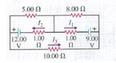
Calculate the three currents I1, I2, and I3 indicated in the circuit diagram shown in Fig. P26.59.
Figure P26.59
Expert Solution & Answer

Learn your wayIncludes step-by-step video

schedule07:45
Students have asked these similar questions
A capacitor of capacitance C is connected to four resistors = 62, R,= 40 R, = 90
and R4 = 652 and a battery
V= 36 V with an open switch.
R,
R,
C
R
R2
What is the current through Ki when the switch has been closed for a long period of time?
Select one:
O a. 3.6 A
O b. 6 A
O C. OA
Od. 2.4 A
12:11 PM
5/13/2021
2o2
3052
352
552
652
2A
A. The power dissipated in the 3 Ohms resistor is
W.
B. The total voltage is
V.
C. The power dissipated in the 5 Ohms resistor is
W.
Round all answers to whole numbers.
What is the current (in A) passing through resistor 3 in the circuit if V = 12 V, R1 = 18 Q, R2 = 6 Q, and R3 = 3 0?
Give your answer as only the numerical value in the SI units specified. e is interpreted as x10^ for use with large or small values; 1.01e2 is interpreted as 1.01 x 10².
R1
R2
R3
Chapter 26 Solutions
University Physics with Modern Physics Plus Mastering Physics with eText -- Access Card Package (14th Edition)
Ch. 26.1 - Suppose all three of the resistors shown in Fig....Ch. 26.2 - Subtract Eq. (1) from Eq. (2) in Example 26.6. To...Ch. 26.3 - You want to measure the current through and the...Ch. 26.4 - The energy stored in a capacitor is equal to...Ch. 26.5 - To prevent the circuit breaker in Example 26.14...Ch. 26 - In which 120-V light bulb does the filament have...Ch. 26 - Two 120-V light bulbs, one 25-W and one 200-W,...Ch. 26 - You connect a number of identical light bulbs to a...Ch. 26 - In the circuit shown in Fig. Q26.4, three...Ch. 26 - If two resistors R1 and R2 (R2 R1) are connected...
Ch. 26 - If two resistors R1 and R2 (R2 R1) are connected...Ch. 26 - A battery with no internal resistance is connected...Ch. 26 - A resistor consists of three identical metal...Ch. 26 - A light bulb is connected in the circuit shown in...Ch. 26 - A real battery, having nonnegligible internal...Ch. 26 - If the battery in Discussion Question Q26.10 is...Ch. 26 - Consider the circuit shown in Fig. Q26.12. What...Ch. 26 - Is it possible to connect resistors together in a...Ch. 26 - The battery in the circuit shown in Fig. Q26.14...Ch. 26 - In a two-cell flashlight, the batteries are...Ch. 26 - Identical light bulbs A, B, and C are connected as...Ch. 26 - The emf of a flashlight battery is roughly...Ch. 26 - Will the capacitors in the circuits shown in Fig....Ch. 26 - Verify that the time constant RC has units of...Ch. 26 - For very large resistances it is easy to construct...Ch. 26 - When a capacitor, battery, and resistor are...Ch. 26 - A uniform wire of resistance R is cut into three...Ch. 26 - A machine part has a resistor X protruding from an...Ch. 26 - A resistor with R1 = 25.0 is connected to a...Ch. 26 - A 42- resistor and a 20- resistor are connected in...Ch. 26 - A triangular array of resistors is shown in Fig....Ch. 26 - For the circuit shown in Fig. E26.6 both meters...Ch. 26 - For the circuit shown in Fig. E26.7 find the...Ch. 26 - Three resistors having resistances of 1.60 , 2.40...Ch. 26 - Now the three resistors of Exercise 26.8 are...Ch. 26 - Power Rating of a Resistor. The power rating of a...Ch. 26 - In Fig. E26.11, R1, = 3.00 , R2 = 6.00 , and R3=...Ch. 26 - In Fig. E26.11 the battery has emf 35.0 V and...Ch. 26 - Compute the equivalent resistance of the network...Ch. 26 - Compute the equivalent resistance of the network...Ch. 26 - In the circuit of Fig. E26.15, each resistor...Ch. 26 - Consider the circuit shown in Fig. E26.16. The...Ch. 26 - In the circuit shown in Fig. E26.17, the voltage...Ch. 26 - In the circuit shown in Fig. E26.18, = 36.0 V,...Ch. 26 - CP In the circuit in Fig. E26.19, a 20.0- resistor...Ch. 26 - In the circuit shown in Fig. E26.20, the rate at...Ch. 26 - Light Bulbs in Series and in Parallel. Two light...Ch. 26 - Light Bulbs in Series. A 60-W, 120-V light bulb...Ch. 26 - In the circuit shown in Fig. E26.23, ammeter A1...Ch. 26 - The batteries shown in the circuit in Fig. E26.24...Ch. 26 - In the circuit shown in Fig. E26.25 find (a) the...Ch. 26 - Find the emfs 1 and 2 in the circuit of Fig....Ch. 26 - In the circuit shown in Fig. E26.27, find (a) the...Ch. 26 - In the circuit shown in Fig. E26.28, find (a) the...Ch. 26 - The 10.00-V battery in Fig. E26.28 is removed from...Ch. 26 - The 5.00-V battery in Fig. E26.28 is removed from...Ch. 26 - In the circuit shown in Fig. E26.31 the batteries...Ch. 26 - In the circuit shown in Fig. E26.32 both batteries...Ch. 26 - In the circuit shown in Fig. E26.33 all meters are...Ch. 26 - In the circuit shown in Fig. E26.34, the 6.0-...Ch. 26 - The resistance of a galvanometer coil is 25.0 ,...Ch. 26 - The resistance of the coil of a pivoted coil...Ch. 26 - A circuit consists of a series combination of...Ch. 26 - A galvanometer having a resistance of 25.0 has a...Ch. 26 - A capacitor is charged to a potential of 12.0 V...Ch. 26 - You connect a battery, resistor, and capacitor as...Ch. 26 - A 4.60-F capacitor that is initially uncharged is...Ch. 26 - You connect a battery, resistor, and capacitor as...Ch. 26 - CP In the circuit shown in Fig. E26.43 both...Ch. 26 - A 12.4-F capacitor is connected through a 0.895-M...Ch. 26 - An emf source with = 120 V, a resistor with R =...Ch. 26 - A resistor and a capacitor are connected in series...Ch. 26 - CP In the circuit shown in Fig. E26.47 each...Ch. 26 - A 1.50-F capacitor is charging through a 12.0-...Ch. 26 - In the circuit in Fig. E26.49 the capacitors are...Ch. 26 - A 12.0-F capacitor is charged to a potential of...Ch. 26 - In the circuit shown in Fig. E26.51, C = 5.90 F, ...Ch. 26 - Prob. 26.52ECh. 26 - A 1500-W electric beater is plugged into the...Ch. 26 - In Fig. P26.54, the battery has negligible...Ch. 26 - The two identical light bulbs in Example 26.2...Ch. 26 - Each of the three resistors in Fig. P26.56 has a...Ch. 26 - (a) Find the potential of point a with respect to...Ch. 26 - CP For the circuit shown in Fig. P26.58 a 20.0-...Ch. 26 - Calculate the three currents I1, I2, and I3...Ch. 26 - What must the emf in Fig. P26.60 be in order for...Ch. 26 - Find the current through each of the three...Ch. 26 - (a) Find the current through the battery and each...Ch. 26 - Consider the circuit shown in Fig. P26.63. (a)...Ch. 26 - In the circuit shown in Fig. P26.64, = 24.0 V,...Ch. 26 - In the circuit shown in Fig. P26.65, the current...Ch. 26 - In the circuit shown in Fig. P26.66 all the...Ch. 26 - Figure P26.67 employs a convention often used in...Ch. 26 - Three identical resistors are connected in series....Ch. 26 - A resistor R1 consumes electrical power P1 when...Ch. 26 - The capacitor in Fig. F26.70 is initially...Ch. 26 - A 2.00-F capacitor that is initially uncharged is...Ch. 26 - A 6.00-F capacitor that is initially uncharged is...Ch. 26 - Point a in Fig. P26.73 is maintained at a constant...Ch. 26 - The Wheatstone Bridge. The circuit shown in Fig....Ch. 26 - (See Problem 26.67.) (a) What is the potential of...Ch. 26 - A 2.36-F capacitor that is initially uncharged is...Ch. 26 - A 224- resistor and a 589- resistor are connected...Ch. 26 - A resistor with R = 850 is connected to the...Ch. 26 - A capacitor that is initially uncharged is...Ch. 26 - DATA You set up the circuit shown in Fig. 26.22a,...Ch. 26 - DATA You set up the circuit shown in Fig. 26.20....Ch. 26 - DATA The electronics supply company where you work...Ch. 26 - An Infinite Network. As shown in Fig. P26.83, a...Ch. 26 - Suppose a resistor R lies along each edge of a...Ch. 26 - BIO Attenuator Chains and Axons. The infinite...Ch. 26 - Assume that a typical open ion channel spanning an...Ch. 26 - In a simple model of an axon conducting a nerve...Ch. 26 - Cell membranes across a wide variety of organisms...
Additional Science Textbook Solutions
Find more solutions based on key concepts
3. What is free-fall, and why does it make you weightless? Briefly describe why astronauts are weightless in th...
The Cosmic Perspective (8th Edition)
Describe at least three characteristics of Greek thinking that helped pave the way for the development of moder...
Life in the Universe (4th Edition)
What class of motion, natural or violent, did Aristotle attribute to motion of the Moon?
Conceptual Physics (12th Edition)
Roughly how long does it take light to travel 1 foot?
Essential University Physics: Volume 2 (3rd Edition)
43. Find the area of a rectangle 4.50 m long and 2.20 m wide.
Applied Physics (11th Edition)
12. (I) Write the following as full (decimal) numbers without prefixes on the units: (a) 286.6mm, (b) 85µV, (c)...
Physics: Principles with Applications
Knowledge Booster


Learn more about
Need a deep-dive on the concept behind this application? Look no further. Learn more about this topic, physics and related others by exploring similar questions and additional content below.Similar questions
- 25.54. In the circuit shown in Fig. P25.54, R is a variable resistor whose value ranges from 0 to co, and a and b are the terminals of a battery that has an emf E = 15.0V and an internal resistance of 4.00 2. The ammeter and voltmeter are idealized meters. As R varies over its full range of values, what will be the largest and smallest readings of (a) the voltmeter and (b) the ammeter? (c) Sketch qualita- tive graphs of the readings of both meters as functions of R. Figure P25.54 Rarrow_forwardConsider the three resistors R1 = 12 Ω, R2 = 39 Ω, and R3 = 78 Ω in the configuration shown in the figure. A potential difference ΔV = 1.5 V is applied between A and B. A. Calculate the numerical value of I2 in A. B. Calculate the numerical value of I3 through R3.arrow_forwardIn the adjacent circuit, the voltages and voalues of resistance are unknown. The value of the current running through R1 is 5.3 mA going from left to right, and the current through R3 is 1.8 mA from the top of R3 to the bottom. The value of the current through R2 running from right to left (in mA) is: R1 R2 R3 V1 V2 O a. 2.65 O b. 10.60 O c.7.10 O d.-3.50 O e. 3.50arrow_forward
- A 1000. µ F uncharged capacitor is connected in series with a 2.00KN resistor. The capacitor will be charged using a 5 V battery such that the whole circuit is connected in series. At t = 0, the switch is closed. What will be the charge when t = 1.5T? О А. 1.12шС оВ. 3.88 mC ос. 3.88дС O D. 1.12 mCarrow_forwardWhen switch S in Fig. E25.33 is open, the voltmeter V of the battery reads 3.08 V. When the switch is closed, the voltmeter reading drops to 2.97 V, and the ammeter A reads 1.65 A. Find the emf, the internal resistance of the battery, and the circuit resistance R. Assume that the two meters are ideal, so they don’t affect the circuit.arrow_forwardA current of I = 4.7 A passes through the circuit shown, where R = 46 Q. I 3R 5R ww ww 2R 6R §2RR ww 10R 5R A. In terms of R, I, and numeric values, write an expression for the voltage of the source, V. B. What is the voltage, V in volts?arrow_forward
- A circuit consisting of 5 resistors is shown in the graph. Their resistances are R1 = 16 Ω, R2 = 35 Ω, R3 = 93 Ω, R4 = 36 Ω, and R5 = 32 Ω, and the emf of the battery is ε = 3.5 V. Suppose the internal resistance of the battery is zero. a. Express the current I through R1 in terms of the emf ε and the equivalent resistance R. b. Express the power P dissipated by R1 through I and R1. c. Calculate the numerical value of I in A. d. Calculate the numerical value of the power P in W.arrow_forwardAn ideal emf ɛ = 12 V is wired into a circuit with resistors R1 = 4.0 N and R2 = 8.0 N, as shown below. R1 R2 a. Find the current in the circuit. b. Identify which resistor dissipates the greatest power and find that power.arrow_forwardThree resistors, R1 = 2.55 Ω, R2 = 4.77 Ω, and R3 = 6.55 Ω are connected by ideal metal wires, as shown in the figure. If the voltage dropping through R1 is 5.51 V, what is the current flowing through R2 (in A)?arrow_forward
- Problem 10arrow_forwardThe current through the 30 Ω resistor shown is measured to be 0.25 A. What is the emf ε of the battery?arrow_forward5.00 120 V 6.00 3110 4.00 8.00 1 2 A. The total currenț through the circuit is B. The voltage across the 8 Ohms resistor is V. C. The power is dissipated in the 5 Ohms resistor is W. Input all answers as whole numbers. A.arrow_forward
arrow_back_ios
SEE MORE QUESTIONS
arrow_forward_ios
Recommended textbooks for you
 Physics for Scientists and Engineers: Foundations...PhysicsISBN:9781133939146Author:Katz, Debora M.Publisher:Cengage Learning
Physics for Scientists and Engineers: Foundations...
Physics
ISBN:9781133939146
Author:Katz, Debora M.
Publisher:Cengage Learning
How To Solve Any Resistors In Series and Parallel Combination Circuit Problems in Physics; Author: The Organic Chemistry Tutor;https://www.youtube.com/watch?v=eFlJy0cPbsY;License: Standard YouTube License, CC-BY