
University Physics, Volume 2 - Technology Update Custom Edition for Texas A&M - College Station, 2/e
1st Edition
ISBN: 9781323390382
Author: YOUNG
Publisher: Pearson Education
expand_more
expand_more
format_list_bulleted
Videos
Textbook Question
Chapter 26, Problem 26.73P
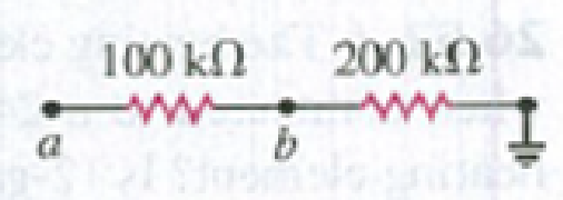
Point a in Fig. P26.73 is maintained at a constant potential of 400 V above ground. (See Problem 26.67.) (a) What is the reading of a voltmeter with the proper range and with resistance 5.00 × 10⁴ Ω when connected between point b and ground? (b) What is the reading of a voltmeter with resistance 5.00 × 10⁶ Ω? (c) What is the reading of a voltmeter with infinite resistance?
Figure P26.73
Expert Solution & Answer
Want to see the full answer?
Check out a sample textbook solution
Students have asked these similar questions
A 3.00 M resistor and a 1.00 mF capacitor are connected in series with an ideal battery of emf e= 4.00 V.At 1.00 s after the connection is made, what is the rate at which (a) the charge of the capacitor is increasing, (b) energy is being stored in the capacitor, (c) thermal energy is appearing in the resistor, and (d) energy is being delivered by the battery?
In the figure the ideal batteries have emfs 1 = 13.1 V and 2 = 4.17 V, and the resistances are each 4.02 Ω. What are the (a) magnitude and (b) direction of i1 and the (c) magnitude and (d) direction of i2? (e) Does battery 1 supply or absorb energy, and (f) what is its energy transfer rate? (g) Does battery 2 supply or absorb energy, and (h) what is its energy transfer rate?
When charging a capacitor in series with a resistor, using a 10 V emf source, what would you expect the voltage of the capacitor to be at an initial time of t = τ ?
a. 3.68 V
b. 0.368 V
c. 6.32 V
d. 10 V
e. 0.632 V
Chapter 26 Solutions
University Physics, Volume 2 - Technology Update Custom Edition for Texas A&M - College Station, 2/e
Ch. 26 - In which 120-V light bulb does the filament have...Ch. 26 - Two 120-V light bulbs, one 25-W and one 200-W,...Ch. 26 - You connect a number of identical light bulbs to a...Ch. 26 - In the circuit shown in Fig. Q26.4, three...Ch. 26 - If two resistors R1 and R2 (R2 R1) are connected...Ch. 26 - If two resistors R1 and R2 (R2 R1) are connected...Ch. 26 - A battery with no internal resistance is connected...Ch. 26 - A resistor consists of three identical metal...Ch. 26 - A light bulb is connected in the circuit shown in...Ch. 26 - A real battery, having nonnegligible internal...
Ch. 26 - If the battery in Discussion Question Q26.10 is...Ch. 26 - Consider the circuit shown in Fig. Q26.12. What...Ch. 26 - Is it possible to connect resistors together in a...Ch. 26 - The battery in the circuit shown in Fig. Q26.14...Ch. 26 - In a two-cell flashlight, the batteries are...Ch. 26 - Identical light bulbs A, B, and C are connected as...Ch. 26 - The emf of a flashlight battery is roughly...Ch. 26 - Will the capacitors in the circuits shown in Fig....Ch. 26 - Verify that the time constant RC has units of...Ch. 26 - For very large resistances it is easy to construct...Ch. 26 - When a capacitor, battery, and resistor are...Ch. 26 - A uniform wire of resistance R is cut into three...Ch. 26 - A machine part has a resistor X protruding from an...Ch. 26 - A resistor with R1 = 25.0 is connected to a...Ch. 26 - A 42- resistor and a 20- resistor are connected in...Ch. 26 - A triangular array of resistors is shown in Fig....Ch. 26 - For the circuit shown in Fig. E26.6 both meters...Ch. 26 - For the circuit shown in Fig. E26.7 find the...Ch. 26 - Three resistors having resistances of 1.60 , 2.40...Ch. 26 - Now the three resistors of Exercise 26.8 are...Ch. 26 - Power Rating of a Resistor. The power rating of a...Ch. 26 - In Fig. E26.11, R1, = 3.00 , R2 = 6.00 , and R3=...Ch. 26 - In Fig. E26.11 the battery has emf 35.0 V and...Ch. 26 - Compute the equivalent resistance of the network...Ch. 26 - Compute the equivalent resistance of the network...Ch. 26 - In the circuit of Fig. E26.15, each resistor...Ch. 26 - Consider the circuit shown in Fig. E26.16. The...Ch. 26 - In the circuit shown in Fig. E26.17, the voltage...Ch. 26 - In the circuit shown in Fig. E26.18, = 36.0 V,...Ch. 26 - CP In the circuit in Fig. E26.19, a 20.0- resistor...Ch. 26 - In the circuit shown in Fig. E26.20, the rate at...Ch. 26 - Light Bulbs in Series and in Parallel. Two light...Ch. 26 - Light Bulbs in Series. A 60-W, 120-V light bulb...Ch. 26 - In the circuit shown in Fig. E26.23, ammeter A1...Ch. 26 - The batteries shown in the circuit in Fig. E26.24...Ch. 26 - In the circuit shown in Fig. E26.25 find (a) the...Ch. 26 - Find the emfs 1 and 2 in the circuit of Fig....Ch. 26 - In the circuit shown in Fig. E26.27, find (a) the...Ch. 26 - In the circuit shown in Fig. E26.28, find (a) the...Ch. 26 - The 10.00-V battery in Fig. E26.28 is removed from...Ch. 26 - The 5.00-V battery in Fig. E26.28 is removed from...Ch. 26 - In the circuit shown in Fig. E26.31 the batteries...Ch. 26 - In the circuit shown in Fig. E26.32 both batteries...Ch. 26 - In the circuit shown in Fig. E26.33 all meters are...Ch. 26 - In the circuit shown in Fig. E26.34, the 6.0-...Ch. 26 - The resistance of a galvanometer coil is 25.0 ,...Ch. 26 - The resistance of the coil of a pivoted coil...Ch. 26 - A circuit consists of a series combination of...Ch. 26 - A galvanometer having a resistance of 25.0 has a...Ch. 26 - A capacitor is charged to a potential of 12.0 V...Ch. 26 - You connect a battery, resistor, and capacitor as...Ch. 26 - A 4.60-F capacitor that is initially uncharged is...Ch. 26 - You connect a battery, resistor, and capacitor as...Ch. 26 - CP In the circuit shown in Fig. E26.43 both...Ch. 26 - A 12.4-F capacitor is connected through a 0.895-M...Ch. 26 - An emf source with = 120 V, a resistor with R =...Ch. 26 - A resistor and a capacitor are connected in series...Ch. 26 - CP In the circuit shown in Fig. E26.47 each...Ch. 26 - A 1.50-F capacitor is charging through a 12.0-...Ch. 26 - In the circuit in Fig. E26.49 the capacitors are...Ch. 26 - A 12.0-F capacitor is charged to a potential of...Ch. 26 - In the circuit shown in Fig. E26.51, C = 5.90 F, ...Ch. 26 - Prob. 26.52ECh. 26 - A 1500-W electric beater is plugged into the...Ch. 26 - In Fig. P26.54, the battery has negligible...Ch. 26 - The two identical light bulbs in Example 26.2...Ch. 26 - Each of the three resistors in Fig. P26.56 has a...Ch. 26 - (a) Find the potential of point a with respect to...Ch. 26 - CP For the circuit shown in Fig. P26.58 a 20.0-...Ch. 26 - Calculate the three currents I1, I2, and I3...Ch. 26 - What must the emf in Fig. P26.60 be in order for...Ch. 26 - Find the current through each of the three...Ch. 26 - (a) Find the current through the battery and each...Ch. 26 - Consider the circuit shown in Fig. P26.63. (a)...Ch. 26 - In the circuit shown in Fig. P26.64, = 24.0 V,...Ch. 26 - In the circuit shown in Fig. P26.65, the current...Ch. 26 - In the circuit shown in Fig. P26.66 all the...Ch. 26 - Figure P26.67 employs a convention often used in...Ch. 26 - Three identical resistors are connected in series....Ch. 26 - A resistor R1 consumes electrical power P1 when...Ch. 26 - The capacitor in Fig. F26.70 is initially...Ch. 26 - A 2.00-F capacitor that is initially uncharged is...Ch. 26 - A 6.00-F capacitor that is initially uncharged is...Ch. 26 - Point a in Fig. P26.73 is maintained at a constant...Ch. 26 - The Wheatstone Bridge. The circuit shown in Fig....Ch. 26 - (See Problem 26.67.) (a) What is the potential of...Ch. 26 - A 2.36-F capacitor that is initially uncharged is...Ch. 26 - A 224- resistor and a 589- resistor are connected...Ch. 26 - A resistor with R = 850 is connected to the...Ch. 26 - A capacitor that is initially uncharged is...Ch. 26 - DATA You set up the circuit shown in Fig. 26.22a,...Ch. 26 - DATA You set up the circuit shown in Fig. 26.20....Ch. 26 - DATA The electronics supply company where you work...Ch. 26 - An Infinite Network. As shown in Fig. P26.83, a...Ch. 26 - Suppose a resistor R lies along each edge of a...Ch. 26 - BIO Attenuator Chains and Axons. The infinite...Ch. 26 - Assume that a typical open ion channel spanning an...Ch. 26 - In a simple model of an axon conducting a nerve...Ch. 26 - Cell membranes across a wide variety of organisms...
Additional Science Textbook Solutions
Find more solutions based on key concepts
The Rankine temperature scale (abbreviatedR) uses the same size degrees as Fahrenheit, but measured up from abs...
An Introduction to Thermal Physics
Consider the change in velocity vector between two points on the velocity diagram that are not consecutive. e.g...
Tutorials in Introductory Physics
32.4 Consider each of the following electric- and magnetic-field orientations. In each ease, what is the direct...
University Physics with Modern Physics (14th Edition)
45. Which should be more stable: the lithium-5 or the lithium-7 isotope?
Conceptual Physical Science (6th Edition)
9. (II) What, approximately, is the percent uncertainty for a measurement given as 1.57 m2?
Physics: Principles with Applications
Knowledge Booster


Learn more about
Need a deep-dive on the concept behind this application? Look no further. Learn more about this topic, physics and related others by exploring similar questions and additional content below.Similar questions
- The duration of a photographic flash is related to an RC time constant, which is 0.100F for a certain camera, (a) If the resistance of the flash lamp is 0.0400 duringdischarge, what is the size of the capacitor supplying its energy? (b) What is the time constant for charging the capacitor, if the charging resistance is 800 k ?arrow_forwardA battery is used to charge a capacitor through a resistor as shown in Figure P27.44. Show that half the energy supplied by the battery appears as internal energy in the resistor and half is stored in the capacitor. Figure P27.44arrow_forwardThe student engineer of a campus radio station wishes to verify the effectiveness of the lightning rod on the antenna mast (Fig. P21.71). The unknown resistance Rx is between points C and E. Point E is a true ground, but it is inaccessible for direct measurement because this stratum is several meters below the Earths surface. Two identical rods are driven into the ground at A and B, introducing an unknown resistance Ry. The procedure is as follows. Measure resistance R1 between points A and B, then connect A and B with a heavy conducting wire and measure resistance R2 between points A and C. (a) Derive an equation for Rx in terms of the observable resistances, R1 and R2. (b) A satisfactory ground resistance would be Rx 2.00 . Is the grounding of the station adequate if measurements give R1 = 13.0 and R2 = 6.00 ? Explain. Figure P21.71arrow_forward
- A capacitor with a capacitance of 3.5 uF is initially uncharged. It is connected in series with a switch of negligible resistance, a resistor with a resistance of 10.5 kOhm, and a battery that has a potential difference of 105V. (a) Immediately after the switch is closed, what is the voltage drop VC, in volts, across the capacitor? (b) Immediately after the switch is closed, what is the voltage drop VR, in volts, across the resistor? (c) Immediately after the switch is closed, what is the current, in amperes, through the resistor? (d) Find an expression for the time after the switch is closed when the current in the resistor equals half its maximum value. (e) What is the charge Q, in microcoulombs, on the capacitor when the current in the resistor equals one half its maximum value.arrow_forwardThe figure shows how a bleeder resistor is used to discharge a capacitor after an electronic device is shut off, allowing a person to work on the electronics with less risk of shock. The resistor has a resistance of 284 kΩΩ. (a) What is the time constant? s ( ± 0.1 s) (b) How long will it take to reduce the voltage on the capacitor to 1.0% of its full value once discharge begins? s ( ± 1 s) (c) If the capacitor is charged to a voltage ?0V0 through a 109 ΩΩ resistance, calculate the time it takes to rise to 0.9?0V0 (This is close to two time constants, but you should calculate it precisely.) ms ( ± 0.1 ms)arrow_forwardWhat is the time constant of the circuit shown in Figure OQ28.7? Each of the five resistors has resistance R. and each of the five capacitors has capacitance C. The internal resistance of the battery is negligible. (a) RC. (b) 5RC. (c) 10RC (d) 25RC (e) none of those answersarrow_forward
- In the figure the ideal batteries have emfs ε1 = 18.2 V, ε2 = 9.68 V, and ε3 = 4.90 V, and the resistances are each 2.00 Ω. What are the (a) size and (b) direction (left or right) of current i1? (c) Does battery 1 supply or absorb energy, and (d) what is its power? (e) Does battery 2 supply or absorb energy, and (f) what is its power? (g) Does battery 3 supply or absorb energy, and (h) what is its power?arrow_forwardA capacitor is charged to a potential of 12.0 V and is then connected to a voltmeter having a total internal resistance of 3.40 MΩ. After a time of 4.00 s the voltmeter reads 3.0 V. What are (a) the capacitance and (b) the time constant of the circuit?arrow_forwardIn the figure the ideal batteries have emfs 1 = 26 V and 2 = 7.0 V and the resistors have resistances R1 = 4.2 Ω and R2 = 8.3 Ω. What are (a) the current, the energy dissipation rate in (b) resistor 1 and (c) resistor 2, and the energy transfer rate in (d) battery 1 and (e) battery 2? Is energy being supplied or absorbed by (f) battery 1 and (g) battery 2?arrow_forward
- The circuit of the figure below shows a capacitor, two ideal batteries, two resistors, and a switch S. Initially S has been open for a long time. If it is then closed for a long time, what is the change in the charge on the capacitor? Assume C = 11 μF, ℰ1 = 1.0 V, ℰ2 = 5.0 V, R1 = 0.30 Ω, and R2 = 0.30 Ω. __________μC (please show the units when working through the problem so that I can follow it easier)arrow_forwardA capacitor with capacitance C = 5 μF is charged to a voltage V = 10V. It is then discharged through a resistor R = 2 MΩ. At what time after the start of the discharge process has the voltage across the capacitor fallen to 1V? Select one: a. 230 msecs b. 23 secs c. 10 secs d. 100 msecsarrow_forwardAn electronic flashgun has a capacitor with capacitance C that is charged to a voltage V. Answer the questions below Given that C=C= 1441 μF and V=V= 317 V. Determine: How much energy is stored by the capacitor? The charge QQ on the capacitor? When the photographer takes a picture, the flash fires for t= 0.0032 ss. What is the average current through the flash tube?arrow_forward
arrow_back_ios
SEE MORE QUESTIONS
arrow_forward_ios
Recommended textbooks for you
 Principles of Physics: A Calculus-Based TextPhysicsISBN:9781133104261Author:Raymond A. Serway, John W. JewettPublisher:Cengage Learning
 Physics for Scientists and EngineersPhysicsISBN:9781337553278Author:Raymond A. Serway, John W. JewettPublisher:Cengage Learning
 Physics for Scientists and Engineers with Modern ...PhysicsISBN:9781337553292Author:Raymond A. Serway, John W. JewettPublisher:Cengage Learning
 Physics for Scientists and Engineers: Foundations...PhysicsISBN:9781133939146Author:Katz, Debora M.Publisher:Cengage Learning
Principles of Physics: A Calculus-Based Text
Physics
ISBN:9781133104261
Author:Raymond A. Serway, John W. Jewett
Publisher:Cengage Learning
Physics for Scientists and Engineers
Physics
ISBN:9781337553278
Author:Raymond A. Serway, John W. Jewett
Publisher:Cengage Learning
Physics for Scientists and Engineers with Modern ...
Physics
ISBN:9781337553292
Author:Raymond A. Serway, John W. Jewett
Publisher:Cengage Learning
Physics for Scientists and Engineers: Foundations...
Physics
ISBN:9781133939146
Author:Katz, Debora M.
Publisher:Cengage Learning
DC Series circuits explained - The basics working principle; Author: The Engineering Mindset;https://www.youtube.com/watch?v=VV6tZ3Aqfuc;License: Standard YouTube License, CC-BY