
Videos
DATA You set up the circuit shown in Fig. 26.20. where C = 5.00 x 10⁻⁶F. At time t = 0. you close the switch and then measure the charge q on the capacitor as a function of the current i in the resistor. Your results are given in the table:
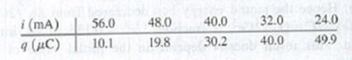
(a) Graph q as a function of i. Explain why the data points, when plotted this way, fall close to a straight line. Find the slope and y-intercept of the straight line that gives the best fit to the data.
(b) Use your results from part (a) to calculate the resistance R of the resistor and the emf ε of the battery, (c) At what time t after the switch is closed is the voltage across the capacitor equal to 10.0 V? (d) When the voltage across the capacitor is 4.00 V. what is the voltage across the resistor?
Want to see the full answer?
Check out a sample textbook solution
Chapter 26 Solutions
University Physics, Volume 2 - Technology Update Custom Edition for Texas A&M - College Station, 2/e
Additional Science Textbook Solutions
Applied Physics (11th Edition)
Essential University Physics: Volume 1 (3rd Edition)
College Physics: A Strategic Approach (4th Edition)
An Introduction to Thermal Physics
Essential University Physics: Volume 2 (3rd Edition)
The Cosmic Perspective (8th Edition)


- When the switch is open in Figure 18.8, power Po is delivered to the resistor R1. When the switch is closed, which of the following is true about the power Pc delivered to R1? (Neglect the internal resistance of the battery.) (a) Pc Po (b) Pc = Po (c) Pc Po Figure 18.8 (Quick Quizzes 18.5 and 18.6)arrow_forwardTwo conducting wires A and B of the same length and radius are connected across the same potential difference. Conductor A has twice the resistivity of conductor B. What is the ratio of the power delivered to A to the power delivered to B? (a) 2 (b) 2 (c) 1 (d) 12 (e)12arrow_forwardIf the terminals of a battery with zero internal resistance are connected across two identical resistors in series, the total power delivered by the battery is 8.00 W. If the same battery is connected across the same resistors in parallel, what is the total power delivered by the battery? (a) 16.0 W (b) 32.0 W (c) 2.00 W (d) 4.00 W (e) none of those answersarrow_forward
- The values of the components in a simple series RC circuit containing a switch (Fig. P21.53) are C = 1.00 F, R = 2.00 106 , and = 10.0 V. At the instant 10.0 s after the switch is closed, calculate (a) the charge on the capacitor, (b) the current in the resistor, (c) the rate at which energy is being stored in the capacitor, and (d) the rate at which energy is being delivered by the battery.arrow_forwardExplain why R=R0(1 + a?T) for the temperature variation of the resistance R of an object is not as accurate as P=P0(1 + a?T) which gives the temperature variation of resistivity P.arrow_forwardDraw two graphs of charge versus time on a capacitor. Draw one for charging an initially uncharged capacitor in series with a resistor, as in the circuit in Figure 21.38, starting from t = 0. Draw the other for discharging a capacitor through a resistor, as in the circuit in Figure 21.39, starting at t = 0, with an initial charge Q0. Show at least two intervals of t.arrow_forward
- (a) Find the current in each resistor of Figure P18.18 by using the rules for resistors in series and parallel. (b) Write three independent equations for the three currents using Kirchhoffs laws: one with the node rule; a second using the loop rule through the battery, the 6.0- resistor, and the 24.0- resistor; and the third using the loop rule through the 12.0- and 24.0- resistors. Solve to check the answers found in part (a). Figure Pl8.18arrow_forward(a) Find the current in each resistor of Figure P18.18 by using the rules for resistors in series and parallel. (b) Write three independent equations for the three currents using Kirchhoffs laws: one with the node rule; a second using the loop rule through the battery, the 6.0- resistor, and the 24.0- resistor; and the third using the loop rule through the 12.0- and 24.0- resistors. Solve to check the answers found in part (a). Figure Pl8.18arrow_forwardElectric current I enters a node with three resistors connected in parallel (Fig. CQ18.5). Which one of the following is correct? (a) I1 = I and I2 = I3 = 0. (b) I2 I1 and I2 I3. (c) V1 V2 V3 (d) I1 I2 I3 0. Figure CQ18.5arrow_forward
- The student engineer of a campus radio station wishes to verify the effectiveness of the lightning rod on the antenna mast (Fig. P21.71). The unknown resistance Rx is between points C and E. Point E is a true ground, but it is inaccessible for direct measurement because this stratum is several meters below the Earths surface. Two identical rods are driven into the ground at A and B, introducing an unknown resistance Ry. The procedure is as follows. Measure resistance R1 between points A and B, then connect A and B with a heavy conducting wire and measure resistance R2 between points A and C. (a) Derive an equation for Rx in terms of the observable resistances, R1 and R2. (b) A satisfactory ground resistance would be Rx 2.00 . Is the grounding of the station adequate if measurements give R1 = 13.0 and R2 = 6.00 ? Explain. Figure P21.71arrow_forwardFigure P18.26 shows a voltage divider, a circuit used to obtain a desired voltage Vout from a source voltage . Determine the required value of R2 if = 5.00 V, Vout = 1.50 V and R1 = 1.00 103 (Hint: Use Kirchhoff's loop rule, substituting Vout = IR2, to find the current. Then solve Ohms law for R2. Figure P18.26arrow_forwardA capacitor with initial charge Q0 is connected across a resistor R at time t = 0. The separation between the plates of the capacitor changes as d = d0/(1 + t) for 0 t 1 s. Find an expression for the voltage drop across the capacitor as a function of time.arrow_forward
 Principles of Physics: A Calculus-Based TextPhysicsISBN:9781133104261Author:Raymond A. Serway, John W. JewettPublisher:Cengage Learning
 College PhysicsPhysicsISBN:9781305952300Author:Raymond A. Serway, Chris VuillePublisher:Cengage Learning
 College PhysicsPhysicsISBN:9781285737027Author:Raymond A. Serway, Chris VuillePublisher:Cengage Learning
 College PhysicsPhysicsISBN:9781938168000Author:Paul Peter Urone, Roger HinrichsPublisher:OpenStax College
 Physics for Scientists and Engineers: Foundations...PhysicsISBN:9781133939146Author:Katz, Debora M.Publisher:Cengage Learning
 Physics for Scientists and Engineers, Technology ...PhysicsISBN:9781305116399Author:Raymond A. Serway, John W. JewettPublisher:Cengage Learning