
PHYSICS F./SCI... W/MOD V.II W/KIT
4th Edition
ISBN: 9780134819884
Author: GIANCOLI
Publisher: PEARSON
expand_more
expand_more
format_list_bulleted
Concept explainers
Videos
Textbook Question
Chapter 26, Problem 50P
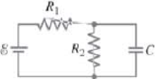
(III) Determine the time constant for charging the capacitor in the circuit of Fig. 26–61. [Hint: Use Kirchhoff’s rules.] (b) What is the maximum charge on the capacitor?
FIGURE 26–61 Problem 50.
Expert Solution & Answer
Want to see the full answer?
Check out a sample textbook solution
Students have asked these similar questions
(b) A student has three capacitors. Two of the capacitors have a capacitance of 4.0 µF and one
has a capacitance of 8.0 µF.
Draw labelled circuit diagrams, one in each case, to show how the three capacitors may be
connected to give a total capacitance of:
(i) 1.6uF
(ii) 10µF.
(I) (a) Six 4.8µF capacitors are connected in parallel.What is the equivalent capacitance? (b) What is their equivalent capacitance if connected in series?
(II) If 21.0 V is applied across
the whole network of Fig. 19–63,
calculate (a) the voltage across
each capacitor and (b) the charge
on each capacitor.
C =
3.00 μF
C2 =
4.00 μF
C3 =
2.00 μF
FIGURE 19-63
V=
Problems 39 and 40.
-21.0 V-
Chapter 26 Solutions
PHYSICS F./SCI... W/MOD V.II W/KIT
Ch. 26.1 - Repeat Example 261 assuming now that the...Ch. 26.2 - You have a 10- and a 15- resistor. What is the...Ch. 26.3 - Write the equation for the lower loop abcdefga of...Ch. 26.4 - If the jumper cables of Example 2610 were...Ch. 26.5 - In 10 times constants, the charge on the capacitor...Ch. 26 - Explain why birds can sit on power lines safely,...Ch. 26 - Discuss the advantages and disadvantages of...Ch. 26 - If all you have is a 120-V line, would it be...Ch. 26 - Two lightbulbs of resistance R1 and R2 (R2 R1)...Ch. 26 - Household outlets are often double outlets. Are...
Ch. 26 - With two identical lightbulbs and two identical...Ch. 26 - If two identical resistors are connected in series...Ch. 26 - You have a single 60-W bulb on in your room. How...Ch. 26 - When applying Kirchhoffs loop rule (such as in...Ch. 26 - Compare and discuss the formulas for resistors and...Ch. 26 - For what use are batteries connected in series?...Ch. 26 - Can the terminal voltage of a battery ever exceed...Ch. 26 - Explain in detail how you could measure the...Ch. 26 - In an RC circuit, current flows from the battery...Ch. 26 - Given the circuit shown in Fig. 2634, use the...Ch. 26 - Figure 2635 is a diagram of a capacitor (or...Ch. 26 - Design a circuit in which two different switches...Ch. 26 - What is the main difference between an analog...Ch. 26 - What would happen if you mistakenly used an...Ch. 26 - Explain why an ideal ammeter would have zero...Ch. 26 - A voltmeter connected across a resistor always...Ch. 26 - A small battery-operated flashlight requires a...Ch. 26 - Different lamps might have batteries connected in...Ch. 26 - Prob. 1PCh. 26 - (I) Four 1.50-V cells are connected in series to a...Ch. 26 - (II) A 1.5-V dry cell can be tested by connecting...Ch. 26 - (II) What is the internal resistance of a 12.0-V...Ch. 26 - (I) A 650- and a 2200- resistor are connected in...Ch. 26 - (I) Three 45- lightbulbs and three 65- lightbulbs...Ch. 26 - (I) Suppose that you have a 680-, a 720-, and a...Ch. 26 - (I) How many 10- resistors must be connected in...Ch. 26 - (II) Suppose that you have a 9.0-V battery and you...Ch. 26 - Three 1.70-k resistors can be connected together...Ch. 26 - (II) A battery with an emf of 12.0 V shows a...Ch. 26 - (II) Eight identical bulbs are connected in series...Ch. 26 - (II) Eight bulbs are connected in parallel to a...Ch. 26 - (II) The performance of the starter circuit in an...Ch. 26 - (II) A close inspection of an electric circuit...Ch. 26 - (II) Determine (a) the equivalent resistance of...Ch. 26 - (II) A 75-W, 110-V bulb is connected in parallel...Ch. 26 - (II) (a) Determine the equivalent resistance of...Ch. 26 - (II) Whal is the net resistance of the circuit...Ch. 26 - (II) Calculate the current through each resistor...Ch. 26 - (II) The two terminals of a voltage source with...Ch. 26 - (II) Two resistors when connected in series to a...Ch. 26 - (III) Three equal resistors (R) are connected to a...Ch. 26 - (III) A 2.8-k and a 3.7-k resistor are connected...Ch. 26 - (III) Consider the network of resistors shown in...Ch. 26 - (III) You are designing a wire resistance heater...Ch. 26 - (I) Calculate the current in the circuit of Fig....Ch. 26 - (II) Determine the terminal voltage of each...Ch. 26 - (II) For the circuit shown in Fig. 2647, find the...Ch. 26 - (II) (a) A network of five equal resistors R is...Ch. 26 - (II) (a) What is the potential difference between...Ch. 26 - (II) Calculate the currents in each resistor of...Ch. 26 - (II) Determine the magnitudes and directions of...Ch. 26 - (II) Determine the magnitudes and directions of...Ch. 26 - (II) A voltage V is applied to n identical...Ch. 26 - (III) (a) Determine the currents I1, I2, and I3 in...Ch. 26 - (III) What would the current I1 be in Fig. 2653 if...Ch. 26 - (III) Determine the current through each of the...Ch. 26 - (III) If the 25- resistor in Fig. 2654 is shorted...Ch. 26 - (III) Twelve resistors, each of resistance R, are...Ch. 26 - (III) Determine the net resistance in Fig. 2656...Ch. 26 - (II) Suppose two batteries, with unequal emfs of...Ch. 26 - (I) Estimate the range of resistance needed to...Ch. 26 - (II) In Fig. 2658 (same as Fig. 2617a), the total...Ch. 26 - (II) Two 3.8-F capacitors, two 2.2-k resistors,...Ch. 26 - (II) How long does it take for the energy stored...Ch. 26 - (II) A parallel-plate capacitor is filled with a...Ch. 26 - (II) The RC circuit of Fig. 2659 (same as Fig....Ch. 26 - (II) Consider the circuit shown in Fig. 2660,...Ch. 26 - (III) Determine the time constant for charging the...Ch. 26 - (III) Two resistors and two uncharged capacitors...Ch. 26 - (III) Suppose the switch S in Fig. 2662 is closed....Ch. 26 - (I) An ammeter has a sensitivity of 35,00 /V. What...Ch. 26 - (I) What is the resistance of a voltmeter on the...Ch. 26 - (II) A galvanometer has a sensitivity of 45 k/V...Ch. 26 - (II) A galvanometer has an internal resistance of...Ch. 26 - (II) A particular digital meter is based on an...Ch. 26 - (II) A milliammeter reads 25 mA full scale. It...Ch. 26 - (II) A 45-V battery of negligible internal...Ch. 26 - (II) An ammeter whose internal resistance is 53 ...Ch. 26 - (II) A battery with E=12.0V and internal...Ch. 26 - (II) A 12.0-V battery (assume the internal...Ch. 26 - (III) Two 9.4-k resistors are placed in series and...Ch. 26 - (III) When the resistor R in Fig. 2664 is 35 , the...Ch. 26 - Suppose that you wish to apply a 0.25-V potential...Ch. 26 - A three-way lightbulb can produce 50 W, 100 W, or...Ch. 26 - Suppose you want to run some apparatus that is 65...Ch. 26 - For the circuit shown in Fig. 2618a, show that the...Ch. 26 - A heart pacemaker is designed to operate at 72...Ch. 26 - Prob. 70GPCh. 26 - A Wheatstone bridge is a type of bridge circuit...Ch. 26 - An unknown length of platinum wire 1.22 mm in...Ch. 26 - The internal resistance of a 1.35-V mercury cell...Ch. 26 - How many 12-W resistors, each of the same...Ch. 26 - A solar cell, 3.0 cm square, has an output of 350...Ch. 26 - A power supply has a fixed output voltage of 12.0...Ch. 26 - The current through the 4.0-k resistor in Fig....Ch. 26 - A battery produces 40.8 V when 7.40 A is drawn...Ch. 26 - In the circuit shown in Fig. 2668, the 33-...Ch. 26 - The current through the 20- resistor in Fig. 2669...Ch. 26 - (a) A voltmeter and an ammeter can be connected as...Ch. 26 - (a) What is the equivalent resistance of the...Ch. 26 - A flashlight bulb rated at 2.0 W and 3.0 V is...Ch. 26 - Some light-dimmer switches use a variable resistor...Ch. 26 - A potentiometer is a device to precisely measure...Ch. 26 - Electronic devices often use an RC circuit to...Ch. 26 - The circuit shown in Fig. 2676 is a primitive...Ch. 26 - Determine the current in each resistor of the...Ch. 26 - In the circuit shown in Fig. 2678, switch S is...Ch. 26 - Figure 2679 shows the circuit for a simple...Ch. 26 - Measurements made on circuits that contain large...Ch. 26 - A typical voltmeter has an internal resistance of...Ch. 26 - (II) An RC series circuit contains a resistor R =...
Additional Science Textbook Solutions
Find more solutions based on key concepts
1. How does the range of refrigerator magnets differ from that of common bar magnets?
Conceptual Physical Science (6th Edition)
Electrostatic exploration Geologists sometimes analyze the distribution of materials under Earth's surface, ma...
College Physics
16.19 BIO For a person with normal hearing, the faintest sound that can be heard at a frequency of 400 Hz has a...
University Physics with Modern Physics (14th Edition)
When a cannon with a long barrel is fired, the force of the expanding gases acts on the cannonball for a relati...
Conceptual Integrated Science
The force, when you push against a wall with your fingers, they bend.
Conceptual Physics (12th Edition)
What is the direction of the magnetic force on the current in each of the six cases?
University Physics Volume 2
Knowledge Booster


Learn more about
Need a deep-dive on the concept behind this application? Look no further. Learn more about this topic, physics and related others by exploring similar questions and additional content below.Similar questions
- Check Your Understanding Determine the net capacitance C of each network of capacitors shown below. Assume the C1= 1.0 pF, C2=2.0pF, C3=4.0pF, and C4=5.0 pF. Find the charge on each capacitor, assuming there is a potential difference of 12.0 V across each network.arrow_forwardCheck Your Understanding The radius of the outer sphere of a spherical capacitor is five times the radius of its inner shell. What are the dimensions of this capacitor if its capacitance is 5.00 pF?arrow_forwardWhen discharging a capacitor, as discussed in conjunction with Figure 21.39, how long does it take for the voltage on the capacitor to reach zero? Is this a problem?arrow_forward
- Check Your Understanding When a cylindrical capacitor is given a charge of 0.500 nC, a potential difference of 20.0 V is measured between the cylinders, (a) What is the capacitance of this system? (b) If the cylinders are 1.0 m long, what is the ratio of their radii?arrow_forwardIn the circuit shown in Fig. 19–93, C¡ = 1.0 µF, C2 = 2.0 µF, C3 = 2.4 µF, and a voltage_ Vab = 24 V is applied across points a and b. After C, is fully charged, the switch is thrown to the right. What is the final charge and potential differ- ence on each capacitor? ao C2 FIGURE 19-93 C3 Problem 97. boarrow_forwardIn Fig. 19–86, let V = 10.0 V and C1=C2= C3 = 25.4 µF. How much energy is stored in the capacitor network (a) as shown, (b) if the capacitors were all in series, and (c) if the capacitors were all in parallel? C2 C3 FIGURE 19-86 Problem 88.arrow_forward
- (II) Two capacitors connected in parallel produce an equivalent capacitance of 35.0 μF but when connected in series the equivalent capacitance is only 4.8 μF. What is the individual capacitance of each capacitor?arrow_forward(II) To get an idea how big a farad is, suppose you want to make a 1-F air-filled parallel-plate capacitor for a circuit you are building. To make it a reasonable size, suppose you limit the plate area to 1.0 cm2 What would the gap have to be between the plates? Is this practically achievable?arrow_forward1) a) As shown in figure given below, a 20 V battery is connected across capacitors of capacitances C=C=3 µF and C3=Cs=2C=2C=4 µF. Find (I) the equivalent capacitance Ceq of the capacitors and the charge stored by Ceq q: of capacitor 2, and V3 and q3 of capacitor 3 (II) Vi and qu of capacitor 1, V2 andarrow_forward
- Calculate the net capacitance of three capacitors of capacitances 2.0-uF, 4.0-uF and 6.0-uF when connected (a) in series and (b) in parallel. [10]arrow_forward(II) Determine the equivalent capacitance between points a and b for the combination of capacitors shown in Fig. 19–64. C3 a ob FIGURE 19-64 Problem 44. C2 C4arrow_forward5. (II) What is the ratio of the voltage V, across capacitor C, in Fig. 19–65 to the voltage V2 across capacitor C,? C2 = 1.0 µF C1 = 1.0 μF 10 V . +C3 = 1.0 µF FIGURE 19-65 Problem 45.arrow_forward
arrow_back_ios
SEE MORE QUESTIONS
arrow_forward_ios
Recommended textbooks for you
 College PhysicsPhysicsISBN:9781938168000Author:Paul Peter Urone, Roger HinrichsPublisher:OpenStax College
College Physics
Physics
ISBN:9781938168000
Author:Paul Peter Urone, Roger Hinrichs
Publisher:OpenStax College
How To Solve Any Circuit Problem With Capacitors In Series and Parallel Combinations - Physics; Author: The Organic Chemistry Tutor;https://www.youtube.com/watch?v=a-gPuw6JsxQ;License: Standard YouTube License, CC-BY