
Videos
Determine the magnitude and coordinate direction angles of the resultant force, and sketch this
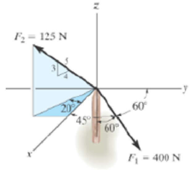
Prob. 2-69

Learn your wayIncludes step-by-step video

Chapter 2 Solutions
Engineering Mechanics: Statics Plus Mastering Engineering with Pearson eText -- Access Card Package (14th Edition) (Hibbeler, The Engineering Mechanics: Statics & Dynamics Series, 14th Edition)
Additional Engineering Textbook Solutions
Mechanics of Materials (10th Edition)
Automotive Technology: Principles, Diagnosis, And Service (6th Edition) (halderman Automotive Series)
Thinking Like an Engineer: An Active Learning Approach (3rd Edition)
Automotive Technology: Principles, Diagnosis, and Service (5th Edition)
Applied Statics and Strength of Materials (6th Edition)
Statics and Mechanics of Materials (5th Edition)


- The mast is subjected to three forces shown. Determine all the coordinate direction angles of F1 So that the resultant force action on the mast is zeroarrow_forwardIf ?=60° and F=450N, Determine the magnitude of the resultant force FR=F1+F2 and its direction, measured counterclockwise from the positive x-axis.arrow_forwardif FB=700N and FC=560N, determine the magnitude and coordinate direction angles of the resultant force acting on the flag pole shown belowarrow_forward
- Determine the magnitude of the resultant force (Fr). And determine the direction of the resultant force, measured counterclockwise from the positive x axis (theta)arrow_forwardDetermine the direction delta of the resultant force acting on the corble measured couterclockwise from the x axi FR= -1790 lbarrow_forward3. Determine the magnitude of the resultant force (Fr). And Determine the direction of the resultant force, measured counter-clockwise from the positive x-axis. (theta)arrow_forward
- Determine the magnitude of the resultant force and its direction measured counterclockwise from the positive x axis.arrow_forwardIf the direction of the resultant force acting on theeyebolt is defined by the unit vector uFR = cos 30°j +sin 30°k,determine the coordinate direction angles of F3 and themagnitude of FR.arrow_forward1a. determine the magnitude of the projected component of F along AC. Express this component as a Cartesian vector. 1b. Determine the angle theta between the pipe segments BA and BC.arrow_forward
- Determine the magnitude and coordinate direction angles (x, y, z) of the resultant force.arrow_forward1. Determine the magnitude of the resultant force (Fr). Determine the direction of the resultant force (theta).arrow_forwardExpress each force acting on the pipe assembly in Cartesian vector formarrow_forward
 Elements Of ElectromagneticsMechanical EngineeringISBN:9780190698614Author:Sadiku, Matthew N. O.Publisher:Oxford University Press
 Mechanics of Materials (10th Edition)Mechanical EngineeringISBN:9780134319650Author:Russell C. HibbelerPublisher:PEARSON
 Thermodynamics: An Engineering ApproachMechanical EngineeringISBN:9781259822674Author:Yunus A. Cengel Dr., Michael A. BolesPublisher:McGraw-Hill Education
 Control Systems EngineeringMechanical EngineeringISBN:9781118170519Author:Norman S. NisePublisher:WILEY
 Mechanics of Materials (MindTap Course List)Mechanical EngineeringISBN:9781337093347Author:Barry J. Goodno, James M. GerePublisher:Cengage Learning
 Engineering Mechanics: StaticsMechanical EngineeringISBN:9781118807330Author:James L. Meriam, L. G. Kraige, J. N. BoltonPublisher:WILEY