
PHYSICS FOR SCIEN & ENGNR W/MOD MAST
4th Edition
ISBN: 9780134112039
Author: GIANCOLI
Publisher: PEARSON
expand_more
expand_more
format_list_bulleted
Concept explainers
Videos
Textbook Question
Chapter 26, Problem 92GP
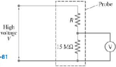
A typical voltmeter has an internal resistance of 10 MΩ and can only measure voltage differences of up to several hundred volts. Figure 26–81 shows the design of a probe to measure a very large voltage difference V using a voltmeter. If you want the voltmeter to read 50 V when V = 50 kV, what value R should be used in this probe?
FIGURE 26-81 Problem 92.
Expert Solution & Answer
Want to see the full answer?
Check out a sample textbook solution
Students have asked these similar questions
A 10^-8 F capacitor (10 nanofarads) is charged to 100 V and then disconnected. One can model the charge leakage of the capacitor with a RC circuit with no voltage source and the resistance of the air between the capacitor plates. On a cold dry day, the resistance of the air gap is 5 x 10^13 ohms; on a humid day, the resistance is 8 x 10^6 ohms. How long will it take the capacitor voltage to dissipate to half its original value on each day?
Two capacitors are connected in series and a source voltage of 75 Volts is applied
across the entire series configuration. If the resistors have values 120 and 50 micro-
Farads, how much charge is on the 120 μF capacitor? Express your answer in micro-
Coulombs (C).
Q. 10. In the two electric circuits shown in the figure,
determine the readings of ideal ammeter (A) and
the ideal voltmeter (V).
A
V
6 V
timm
19
9 V
+|m
w
1Ω
(a)
A
+
V
6 V
Huw
ww
19
9 V
192
(b)
Chapter 26 Solutions
PHYSICS FOR SCIEN & ENGNR W/MOD MAST
Ch. 26.1 - Repeat Example 261 assuming now that the...Ch. 26.2 - You have a 10- and a 15- resistor. What is the...Ch. 26.3 - Write the equation for the lower loop abcdefga of...Ch. 26.4 - If the jumper cables of Example 2610 were...Ch. 26.5 - In 10 times constants, the charge on the capacitor...Ch. 26 - Explain why birds can sit on power lines safely,...Ch. 26 - Discuss the advantages and disadvantages of...Ch. 26 - If all you have is a 120-V line, would it be...Ch. 26 - Two lightbulbs of resistance R1 and R2 (R2 R1)...Ch. 26 - Household outlets are often double outlets. Are...
Ch. 26 - With two identical lightbulbs and two identical...Ch. 26 - If two identical resistors are connected in series...Ch. 26 - You have a single 60-W bulb on in your room. How...Ch. 26 - When applying Kirchhoffs loop rule (such as in...Ch. 26 - Compare and discuss the formulas for resistors and...Ch. 26 - For what use are batteries connected in series?...Ch. 26 - Can the terminal voltage of a battery ever exceed...Ch. 26 - Explain in detail how you could measure the...Ch. 26 - In an RC circuit, current flows from the battery...Ch. 26 - Given the circuit shown in Fig. 2634, use the...Ch. 26 - Figure 2635 is a diagram of a capacitor (or...Ch. 26 - Design a circuit in which two different switches...Ch. 26 - What is the main difference between an analog...Ch. 26 - What would happen if you mistakenly used an...Ch. 26 - Explain why an ideal ammeter would have zero...Ch. 26 - A voltmeter connected across a resistor always...Ch. 26 - A small battery-operated flashlight requires a...Ch. 26 - Different lamps might have batteries connected in...Ch. 26 - Prob. 1PCh. 26 - (I) Four 1.50-V cells are connected in series to a...Ch. 26 - (II) A 1.5-V dry cell can be tested by connecting...Ch. 26 - (II) What is the internal resistance of a 12.0-V...Ch. 26 - (I) A 650- and a 2200- resistor are connected in...Ch. 26 - (I) Three 45- lightbulbs and three 65- lightbulbs...Ch. 26 - (I) Suppose that you have a 680-, a 720-, and a...Ch. 26 - (I) How many 10- resistors must be connected in...Ch. 26 - (II) Suppose that you have a 9.0-V battery and you...Ch. 26 - Three 1.70-k resistors can be connected together...Ch. 26 - (II) A battery with an emf of 12.0 V shows a...Ch. 26 - (II) Eight identical bulbs are connected in series...Ch. 26 - (II) Eight bulbs are connected in parallel to a...Ch. 26 - (II) The performance of the starter circuit in an...Ch. 26 - (II) A close inspection of an electric circuit...Ch. 26 - (II) Determine (a) the equivalent resistance of...Ch. 26 - (II) A 75-W, 110-V bulb is connected in parallel...Ch. 26 - (II) (a) Determine the equivalent resistance of...Ch. 26 - (II) Whal is the net resistance of the circuit...Ch. 26 - (II) Calculate the current through each resistor...Ch. 26 - (II) The two terminals of a voltage source with...Ch. 26 - (II) Two resistors when connected in series to a...Ch. 26 - (III) Three equal resistors (R) are connected to a...Ch. 26 - (III) A 2.8-k and a 3.7-k resistor are connected...Ch. 26 - (III) Consider the network of resistors shown in...Ch. 26 - (III) You are designing a wire resistance heater...Ch. 26 - (I) Calculate the current in the circuit of Fig....Ch. 26 - (II) Determine the terminal voltage of each...Ch. 26 - (II) For the circuit shown in Fig. 2647, find the...Ch. 26 - (II) (a) A network of five equal resistors R is...Ch. 26 - (II) (a) What is the potential difference between...Ch. 26 - (II) Calculate the currents in each resistor of...Ch. 26 - (II) Determine the magnitudes and directions of...Ch. 26 - (II) Determine the magnitudes and directions of...Ch. 26 - (II) A voltage V is applied to n identical...Ch. 26 - (III) (a) Determine the currents I1, I2, and I3 in...Ch. 26 - (III) What would the current I1 be in Fig. 2653 if...Ch. 26 - (III) Determine the current through each of the...Ch. 26 - (III) If the 25- resistor in Fig. 2654 is shorted...Ch. 26 - (III) Twelve resistors, each of resistance R, are...Ch. 26 - (III) Determine the net resistance in Fig. 2656...Ch. 26 - (II) Suppose two batteries, with unequal emfs of...Ch. 26 - (I) Estimate the range of resistance needed to...Ch. 26 - (II) In Fig. 2658 (same as Fig. 2617a), the total...Ch. 26 - (II) Two 3.8-F capacitors, two 2.2-k resistors,...Ch. 26 - (II) How long does it take for the energy stored...Ch. 26 - (II) A parallel-plate capacitor is filled with a...Ch. 26 - (II) The RC circuit of Fig. 2659 (same as Fig....Ch. 26 - (II) Consider the circuit shown in Fig. 2660,...Ch. 26 - (III) Determine the time constant for charging the...Ch. 26 - (III) Two resistors and two uncharged capacitors...Ch. 26 - (III) Suppose the switch S in Fig. 2662 is closed....Ch. 26 - (I) An ammeter has a sensitivity of 35,00 /V. What...Ch. 26 - (I) What is the resistance of a voltmeter on the...Ch. 26 - (II) A galvanometer has a sensitivity of 45 k/V...Ch. 26 - (II) A galvanometer has an internal resistance of...Ch. 26 - (II) A particular digital meter is based on an...Ch. 26 - (II) A milliammeter reads 25 mA full scale. It...Ch. 26 - (II) A 45-V battery of negligible internal...Ch. 26 - (II) An ammeter whose internal resistance is 53 ...Ch. 26 - (II) A battery with E=12.0V and internal...Ch. 26 - (II) A 12.0-V battery (assume the internal...Ch. 26 - (III) Two 9.4-k resistors are placed in series and...Ch. 26 - (III) When the resistor R in Fig. 2664 is 35 , the...Ch. 26 - Suppose that you wish to apply a 0.25-V potential...Ch. 26 - A three-way lightbulb can produce 50 W, 100 W, or...Ch. 26 - Suppose you want to run some apparatus that is 65...Ch. 26 - For the circuit shown in Fig. 2618a, show that the...Ch. 26 - A heart pacemaker is designed to operate at 72...Ch. 26 - Prob. 70GPCh. 26 - A Wheatstone bridge is a type of bridge circuit...Ch. 26 - An unknown length of platinum wire 1.22 mm in...Ch. 26 - The internal resistance of a 1.35-V mercury cell...Ch. 26 - How many 12-W resistors, each of the same...Ch. 26 - A solar cell, 3.0 cm square, has an output of 350...Ch. 26 - A power supply has a fixed output voltage of 12.0...Ch. 26 - The current through the 4.0-k resistor in Fig....Ch. 26 - A battery produces 40.8 V when 7.40 A is drawn...Ch. 26 - In the circuit shown in Fig. 2668, the 33-...Ch. 26 - The current through the 20- resistor in Fig. 2669...Ch. 26 - (a) A voltmeter and an ammeter can be connected as...Ch. 26 - (a) What is the equivalent resistance of the...Ch. 26 - A flashlight bulb rated at 2.0 W and 3.0 V is...Ch. 26 - Some light-dimmer switches use a variable resistor...Ch. 26 - A potentiometer is a device to precisely measure...Ch. 26 - Electronic devices often use an RC circuit to...Ch. 26 - The circuit shown in Fig. 2676 is a primitive...Ch. 26 - Determine the current in each resistor of the...Ch. 26 - In the circuit shown in Fig. 2678, switch S is...Ch. 26 - Figure 2679 shows the circuit for a simple...Ch. 26 - Measurements made on circuits that contain large...Ch. 26 - A typical voltmeter has an internal resistance of...Ch. 26 - (II) An RC series circuit contains a resistor R =...
Additional Science Textbook Solutions
Find more solutions based on key concepts
A friend says, “It makes no sense that Anna could turn on lights in her hands simultaneously in her frame but t...
Modern Physics
42. A lens with a focal length of 25 cm is placed 40 cm in front of a lens with a focal length of 5.0 cm. How f...
College Physics: A Strategic Approach (4th Edition)
When the dinosaurs were the dominant land species, was Earths climate warmer, cooler, or the same compared to m...
Conceptual Integrated Science
24.3 Gratings: an application of interference
12. * Purchase a grating How many lines per centimeter should a g...
College Physics
A block 20% more massive than you hangs from a rope that goes over a frictionless, massless pulley. With what a...
Essential University Physics: Volume 1 (3rd Edition)
Jupiter Mass. Jupiter’s moon Io orbits Jupiter every 42.5 hours at an average distance of 422,000 kilometers fr...
Life in the Universe (4th Edition)
Knowledge Booster


Learn more about
Need a deep-dive on the concept behind this application? Look no further. Learn more about this topic, physics and related others by exploring similar questions and additional content below.Similar questions
- Power P0 = I0 V0 is delivered to a resistor of resistance R0. If the resistance is doubled (Rnew = 2R0) while the voltage is adjusted such that the current is constant, what are the ratios (a) Pnew/P0 and (b) Vnew/V0? If, instead, the resistance is held constant while Pnew = 2P0, what are the ratios (c) Vnew/V0, and (d) Inew/I0?arrow_forward(a) Copper Copper Nichrome In the circuit shown in the diagram, two thick wires connect a 1.6 volt battery to a Nichrome (NiCr) wire. Each thick connecting wire is 14 cm long, and has a radius of 9 mm. The thick wires are made of copper, which has 8.44 -1028 mobile electrons per cubic meter, and an electron mobility of 0.00424 (m/s)/(V/m). The Nichrome wire is 5 cm long, and has a radius of 4 mm. Nichrome has 9.1 -1028 mobile electrons per cubic meter, and an electron mobility of 7.1E-5 (m/s)/(V/m). What is the magnitude of the electric field in the thick copper wire? 13.571 (b) What is the magnitude of the electric field in the thin Nichrome wire? V/m V/marrow_forwardA 10 mF capacitor is charged to a voltage of 200 V and discharged through a resistor. How much energy is given to the resistor during the discharge?arrow_forward
- A controller on an electronic arcade game consists of a variable resistor connected across the plates of a 0.252 uF capacitor. The capacitor is charged to 5.16 V, then discharged through the resistor. The time for the potential difference across the plates to decrease to 0.833 V is measured by a clock inside the game. If the range of discharge times that can be handled effectively is from 10.4 us to 6.01 ms, what should be the (a) lower value and (b) higher value of the resistance range of the resistor? (a) Number Units (b) Number Unitsarrow_forward87 The circuit of Fig. 27-75 shows a capacitor, two ideal batteries, two resistors, and a switch S. Initially S has been open for a long time. If it is then closed for a long time, what is the change in the charge on the capacitor? Assume C = 10 µF, E, = 1.0 V, 82 = 3.0 Figure 27-75 Problem 87. V, R = 0.20 0, and R2 = 0.40 N. R2arrow_forwardA 10-9-F capacitor (1 nanofarad) is charged to 100 V and then disconnected. One can model the charge leakage of the capacitor with a RC circuit with no voltage source and the resistance of the air between the capacitor plates. On a cold dry day, the resistance of the air gap is 5x 10¹³ 2; on a humid day, the resistance is 6x 10° 2. How long will it take the capacitor voltage to dissipate to half its original value on each day? On the dry day, it will take seconds. (Use scientific notation. Round to three decimal places as needed.)arrow_forward
- A 10-7.F capacitor (100 nanofarads) is charged to 50 V and then disconnected. One can model the charge leakage of the capacitor with a RC circuit with no voltage source and the resistance of the air between the capacitor plates. On a cold dry day, the resistance of the air gap is 3× 10¹⁸ 2; on a humid day, the resistance is 4 x 10° 2. How long will it take the capacitor voltage to dissipate to half its original value on each day?arrow_forwardQuestion 2: From the following graph, calculate the approximate values of RC time constant when (a) the capacitor is charging and (b) discharging. 100% 90% 80% 70% 60% 50% 40% 30% 20% 10% Time (in seconds) Percentage of Chargearrow_forwardA capacitor of capacitance C = 2x 10^-6 is discharged through a resistor of resistance = 10^5 ohm. When will the energy stored in a capacitor reduce to one-third of its initial valuearrow_forward
- According to the figure, how many V is the voltage value between cb? a) 3 B) one NS) 4 D) -one TO) 15arrow_forward(b) Consider a particular phone that has a battery rated at 4,000 mAh. The battery operates at a potential difference of 3.90 V. How much energy, in units of kilowatt-hours, is stored in a fully charged battery? kWh (c) If electricity costs $0.12 (or 12.0 cents) per kilowatt-hour, what is the value of the total amount of energy stored in this battery? Express your answer in cents (or 0.01 of a dollar). ¢ (d) When the phone is idle (that is, turned on but not making calls or texts, using GPS, or running any power-hungry apps), it will operate continuously for 29.2 hours from a fully charged battery, until the battery runs out. How much average current does the phone draw while idle? Express your answer in milliamperes. mAarrow_forwardR V1 V2 V3 VA Vs Ideal voltmeters are set to read five effective values and connected as shown. Let R = 200 N, L = 0,40, C=6 µF and Vmax = 33 V. When w=1150 rad/s, find the values measured by each voltmeterin Volt unit. a) V, = 13,8; V2 = 27,6; V3 = 11,5; V4 = 16,1; Vs = 21,2 b) V, = 13,3; V, = 28;V3 = 10,6; V, = 17,4; V5 = 21,9 %3D c) V, = 12,9; V2 = 28,4; V3 = 9,77; V, = 18,6; Vs = 22,6 %3D d) V, = 12,5; V, = 28,8; V3 = 9,06; V4 = 19,7; V5 = 23,3 %3D e) V, = 12,2; V2 = 29,2; V3 = 8,44; V4 = 20,7; Vs = 24 %3Darrow_forward
arrow_back_ios
SEE MORE QUESTIONS
arrow_forward_ios
Recommended textbooks for you
 College PhysicsPhysicsISBN:9781305952300Author:Raymond A. Serway, Chris VuillePublisher:Cengage Learning
 College PhysicsPhysicsISBN:9781285737027Author:Raymond A. Serway, Chris VuillePublisher:Cengage Learning
College Physics
Physics
ISBN:9781305952300
Author:Raymond A. Serway, Chris Vuille
Publisher:Cengage Learning
College Physics
Physics
ISBN:9781285737027
Author:Raymond A. Serway, Chris Vuille
Publisher:Cengage Learning
How To Solve Any Circuit Problem With Capacitors In Series and Parallel Combinations - Physics; Author: The Organic Chemistry Tutor;https://www.youtube.com/watch?v=a-gPuw6JsxQ;License: Standard YouTube License, CC-BY