Videos
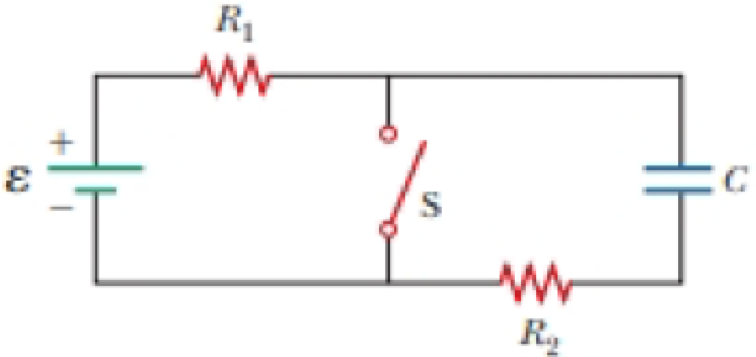
In the circuit of Figure P27.25, the switch S has been open for a long time. It is then suddenly closed. Determine the time constant (a) before the switch is closed and (b) after the switch is closed. (c) Let the switch be closed at t = 0. Determine the current in the switch as a function of time.
Figure P27.25 Problems 25 and 26.
Want to see the full answer?
Check out a sample textbook solution
Chapter 27 Solutions
Bundle: Physics For Scientists And Engineers With Modern Physics, Loose-leaf Version, 10th + Webassign Printed Access Card For Serway/jewett's Physics For Scientists And Engineers, 10th, Single-term
Additional Science Textbook Solutions
Cosmic Perspective Fundamentals
University Physics (14th Edition)
Physics for Scientists and Engineers with Modern Physics
Physics for Scientists and Engineers: A Strategic Approach, Vol. 1 (Chs 1-21) (4th Edition)
Conceptual Physics (12th Edition)
Conceptual Physical Science (6th Edition)


- In the circuit of Figure P27.25, the switch S has been open for a long time. It is then suddenly closed. Take = 10.0 V, R1 = 50.0 k, R2 = 100 k, and C = 10.0 F. Determine the time constant (a) before the switch is closed and (b) after the switch is closed. (c) Let the switch be closed at t = 0. Determine the current in the switch as a function of time. Figure P27.25 Problems 25 and 26.arrow_forwardIn the circuit of Figure P21.57, the switch S has been open for a long time. It is then suddenly closed. Take = 10.0 V, R1 = 50.0 k, R2 = 100 k, and C = 10.0 F. Determine the time constant (a) before the switch is closed and (b) after the switch is closed. (c) Let the switch be closed at t = 0. Determine the current in the switch as a function of time.arrow_forwardEach of the three situations in Figure P32.68 shows a resistor in a circuit in which currents are induced. Using Lenzs law, determine whether the current in each situation is from a to b or from b to a. a. If the current I in the wire in Figure P32.68A is increased from zero to I, what is the direction of the current induced across the resistor R? b. The switch in Figure P32.68B is initially closed and is thrown open at t = 0. What is the direction of the current induced across the resistor R immediately afterward? c. A bar magnet is brought close to the circuit shown in Figure P32.68C. What is the direction of the current induced across the resistor R?arrow_forward
- You connect a battery, resistor, and capacitor as in (Figure 1), where R = 14.0 Ω and C = 3.00 ×10^-6 F. The switch S is closed at t = 0. When the current in the circuit has magnitude 3.00 A, the charge on the capacitor is 40.0 × 10^−6 C. At what time t after the switch is closed is the charge on the capacitor equal to 40.0 x 10^-6 C? When the current has magnitude 3.00 A, at what rate is energy being stored in the capacitor?arrow_forwardChapter 32, Problem 018 Your answer is partially correct. Try again. The circuit in the figure consists of switch S, a 4.50 V ideal battery, a 35.0 M2 resistor, and an airfilled capacitor. The capacitor has parallel circular plates of radius 5.10 cm, separated by 1.50 mm. At time t = 0, switch S is closed to begin charging the capacitor. The electric field between the plates is uniform. At t = 160 µs, what is the magnitude of the magnetic field within the capacitor, at radial distance 3.30 cm? S R Number Units Use correct number of significant digits; the tolerance is +/-1 in the 3rd significant digitarrow_forwardChapter 32, Problem 018 Your answer is partially correct. Try again. The circuit in the figure consists of switch S, a 4.50 V ideal battery, a 35.0 M2 resistor, and an airfilled capacitor. The capacitor has parallel circular plates of radius 5.10 cm, separated by 1.50 mm. At time t = 0, switch S is closed to begin charging the capacitor. The electric field between the plates is uniform. At t = 160 µs, what is the magnitude of the magnetic field within the capacitor, at radial distance 3.30 cm? C S R Number Units T. Use correct number of significant digits; the tolerance is +/-1 in the 3rd significant digitarrow_forward
- The capacitor in the circuit shown below is initially uncharged. The switch is closed at t = 0 s. AV battery = 30 V, C = 3.0 F, and R = 2.0 2. At sometime after the switch is closed, the current in the circuit is measured to be 9.3 A. What is the charge on the capacitor at this time, in Coulomb? Your answer needs to have 2 significant figures, including the negative sign in your answer if needed. Do not include the positive sign if the answer is positive. No unit is needed in your answer, it is already given in the question statement.arrow_forwardSwitch S shown in Figure P28.71 has been closed for a long lime, and the electric circuit carries a constant current. Take C1 = 3.00 μF, C2 = 6.00 μF, R1 = 4.00 kΩ, and R2 , = 7.00 kΩ. The power delivered to R2 , is 2.40 W. (a) Find the charge on C1 . (b) Now the switch is opened. After many milliseconds, by how much has the charge on C2 changed?arrow_forwardChapter 30, Problem 054 In the figure, ε = 118 V, R₁ = 14.9 №, R₂ = 21.3 N, R3 = 35.8 №, and L= 1.90 H. Immediately after switch S is closed, what are (a) i₁ and (b) i₂? (Let currents in the indicated directions have positive values and currents in the opposite directions have negative values.) A long time later, what are (c) ₁ and (d) i2? The switch is then reopened. Just then, what are (e) ₁ and (f) i₂? A long time later, what are (g) ₁ and (h) i₂? www R₁ R$ R₂ Larrow_forward
- 78. A In the RC circuit shown in Figure FOR P29.78, an ideal battery with emf CHEST E and internal resistance r is con- no bruta 101 nected to capacitor C. The switch OTU S is initially open and the capacitor noilor is uncharged. At t = 0, the switch 20 is closed. srit word or abs gnizu dmod odi unslaviups 15/vol S ε reutills α.— himmisiob of W+0.000 21 d I f es bspar 21251 in 152 s ban a. Determine the charge q on the capacitor at time t. Tro b. Find the current in the branch b-e at time t. What is the the 1569 € 210121231 910 current as t goes to infinity? 100% www r b e digi Div ST 0 R + 20, 251 29gnado 101000 9.00 V bilov adi tol noia201qzs FIGURE P29.77 5.00 265 Ω www STEVO R www.c FIGURE P29.78 poses. 79. N A 12.0-V battery is used to cho **** 21 memisa M.ET C - - с d b bes 19lbbigarrow_forwardThe switch in the circuit below has been in position a for a long time. At time t = 0 the switch is thrown to position b. You are given the data: Vb = 36 V, C = 8 μF. Vc is the voltage across the capacitor. If the charge on the capacitor at time t = 0.3 msec after the switch is thrown is 54.1 μC, what is the value of the resistor R? a) 89.71 Ω b) 44.86 Ω c) 22.43 Ω d) Not enough information.arrow_forwardA capacitor, resistor, and an open switch are attached in series as seen below. Initially the switch is open with the capacitor charged. The switch is then closed at time t = 0.00 s. At some time later, the current across the resistor is measured to be 4.0 mA. If the capacitance of the capacitor is 6.6 μF and the resistance of the resistor is 8.8 k, what is the charge on the capacitor in μC? di Sarrow_forward
 Physics for Scientists and EngineersPhysicsISBN:9781337553278Author:Raymond A. Serway, John W. JewettPublisher:Cengage Learning
 Physics for Scientists and Engineers with Modern ...PhysicsISBN:9781337553292Author:Raymond A. Serway, John W. JewettPublisher:Cengage Learning
 Principles of Physics: A Calculus-Based TextPhysicsISBN:9781133104261Author:Raymond A. Serway, John W. JewettPublisher:Cengage Learning
 Physics for Scientists and Engineers: Foundations...PhysicsISBN:9781133939146Author:Katz, Debora M.Publisher:Cengage Learning