Bundle: Physics For Scientists And Engineers With Modern Physics, Loose-leaf Version, 10th + Webassign Printed Access Card For Serway/jewett's Physics For Scientists And Engineers, 10th, Single-term
10th Edition
ISBN: 9781337888585
Author: Raymond A. Serway, John W. Jewett
Publisher: Cengage Learning
expand_more
expand_more
format_list_bulleted
Videos
Textbook Question
Chapter 27, Problem 36AP
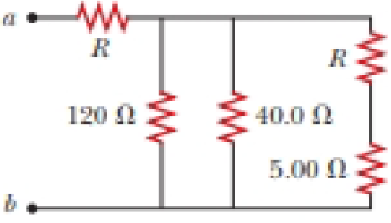
The resistance between terminals a and b in Figure P27.36 is 75.0 Ω. If the resistors labeled R have the same value, determine R.
Figure P27.36
Expert Solution & Answer
Want to see the full answer?
Check out a sample textbook solution
Students have asked these similar questions
Two resistors, R1 = 50 Ω and R2 = 17 Ω are connected in series to a battery providing voltage ΔVbat = 3.1 V. What is the potential difference measured across the resistor R2?
Two resistors, R1 = 21 Ω and R2 = 35 Ω are connected in parallel across a battery providing voltage ΔVbat = 5.7 V. What is the current through resistor R1?
The circuit in Figure P27.41 contains two resistors, R1 = 2.00 kΩ and R2 = 3.00 kΩ, and two capacitors, C1 = 2.00 μF and C2 = 3.00 μF, connected to a battery with emf ε = 120 V. If there are no charges on the capacitors before switch S is closed, determine the charges on capacitors (a) C1 and (b) C2 as functions of time, after the switch is closed.
Chapter 27 Solutions
Bundle: Physics For Scientists And Engineers With Modern Physics, Loose-leaf Version, 10th + Webassign Printed Access Card For Serway/jewett's Physics For Scientists And Engineers, 10th, Single-term
Ch. 27.1 - To maximize the percentage of the power from the...Ch. 27.2 - With the switch in the circuit of Figure 27.4a...Ch. 27.2 - With the switch in the circuit of Figure 27.6a...Ch. 27.2 - Prob. 27.4QQCh. 27.4 - Consider the circuit in Figure 27.17 and assume...Ch. 27 - Two 1.50-V batterieswith their positive terminals...Ch. 27 - As in Example 27.2, consider a power supply with...Ch. 27 - Figure P27.3 shows the interior of a three-way...Ch. 27 - Prob. 4PCh. 27 - Consider the two circuits shown in Figure P27.5 in...
Ch. 27 - Consider strings of incandescent lights that are...Ch. 27 - You are working at an electronics fabrication...Ch. 27 - In your new job at an engineering company, your...Ch. 27 - A battery with = 6.00 V and no internal...Ch. 27 - A battery with emf and no internal resistance...Ch. 27 - Todays class on current and resistance is about to...Ch. 27 - Why is the following situation impossible? A...Ch. 27 - Calculate the power delivered to each resistor in...Ch. 27 - For the purpose of measuring the electric...Ch. 27 - Four resistors are connected to a battery as shown...Ch. 27 - You have a faculty position at a community college...Ch. 27 - The circuit shown in Figure P27.17 is connected...Ch. 27 - The following equations describe an electric...Ch. 27 - Taking R = 1.00 k and = 250 V in Figure P27.19,...Ch. 27 - In the circuit of Figure P27.20, the current I1 =...Ch. 27 - (a) Can the circuit shown in Figure P27.21 be...Ch. 27 - For the circuit shown in Figure P27.22, we wish to...Ch. 27 - An uncharged capacitor and a resistor are...Ch. 27 - Prob. 24PCh. 27 - In the circuit of Figure P27.25, the switch S has...Ch. 27 - In the circuit of Figure P27.25, the switch S has...Ch. 27 - A 10.0-F capacitor is charged by a 10.0-V battery...Ch. 27 - Prob. 28PCh. 27 - Prob. 29PCh. 27 - Prob. 30PCh. 27 - Prob. 31PCh. 27 - Prob. 32APCh. 27 - Find the equivalent resistance between points a...Ch. 27 - The circuit in Figure P27.34a consists of three...Ch. 27 - The circuit in Figure P27.35 has been connected...Ch. 27 - The resistance between terminals a and b in Figure...Ch. 27 - (a) Calculate the potential difference between...Ch. 27 - Why is the following situation impossible? A...Ch. 27 - When two unknown resistors are connected in series...Ch. 27 - Prob. 40APCh. 27 - The circuit in Figure P27.41 contains two...Ch. 27 - Prob. 42APCh. 27 - A power supply has an open-circuit voltage of 40.0...Ch. 27 - A battery is used to charge a capacitor through a...Ch. 27 - Prob. 45APCh. 27 - (a) Determine the equilibrium charge on the...Ch. 27 - In Figure P27.47, suppose the switch has been...Ch. 27 - Figure P27.48 shows a circuit model for the...Ch. 27 - The student engineer of a campus radio station...Ch. 27 - Prob. 50APCh. 27 - The switch in Figure P27.51a closes when Vc23Vand...
Knowledge Booster


Learn more about
Need a deep-dive on the concept behind this application? Look no further. Learn more about this topic, physics and related others by exploring similar questions and additional content below.Similar questions
- A heart pacemaker fires exactly 71 times a minute. Each time it fires, a 19.0 nF capacitor is charged by a battery in series with a resistor to 0.582 of its full voltage. What is the value of the resistance R? R =arrow_forwardThree resistors, R1 = 17.3, R2 = 13.2, R3 = 78, are connected in series across a 16.6 V battery. What is the voltage drop (in Volts) across R1?arrow_forwardA heart pacemaker fires exactly 71 times a minute. Each time it fires, a 19.0 nF capacitor is charged by a battery in series with a resistor to 0.582 of its full voltage. What is the value of the resistance R?arrow_forward
- The emf source, E. of the circuit shown in the figure has negligible internal resistance. The resistors have resistances R= 6.62 and R,=4.92. The capacitor has a capacitance C 13.4 uF When the capacitor is fully charged, the magnitude of the charge on its plates is Q 17.1 uC. What is E in units of Volts? R2 O 4.4 O 2.2 R1 O 3.1 O 0.22 O 1.1arrow_forwardThree resistors are connected as shown below. R1 = 3.0 Ω, R2 = 6.0 Ω, and R3 = 8.0 Ω. The voltage across the battery is 60 V. What is the current through R1, in Amperes?arrow_forwardTwo batteries with emf ℰ = 10 V and internal resistance r = 4 Ω and a resistor with R0 = 45 Ω are connected in series as shown in the figure. a. Express the total resistance, R, in terms of r and R0. b. Express the current, I, in terms of the emf, ℰ, and the total resistance, R. c. Express the voltage, ΔV, across the resister in terms of I and R0. d. Calculate the value of ΔV in volts.arrow_forward
- A capacitor with a capacitance of 3.5 μF is initially uncharged. It is connected in series with a switch of negligible resistance, a resistor with a resistance of 19 kΩ, and a battery that has a potential difference of 170 V. a. Immediately after the switch is closed, what is the voltage drop VC, in volts, across the capacitor? b. Immediately after the switch is closed, what is the voltage drop VR, in volts, across the resistor? c. Immediately after the switch is closed, what is the current, in amperes, through the resistor? d. Find an expression for the time after the switch is closed when the current in the resistor equals half its maximum value. e. What is the charge Q, in microcoulombs, on the capacitor when the current in the resistor equals one half its maximum value.arrow_forwardIn the circuit pictured, the resistors have values of R1 = 170 Q, R, = 62 Q, and R3 = 130 Q, and the battery has an emf ɛ = 274 V. R R2 R3 A. How much current ibatt, in amperes, goes through the battery? B. What is the current i2, in amperes, through resistor R2?arrow_forwardIn the circuit pictured, the resistors have values of R1 = 165 Ω, R2 = 88 Ω, and R3 = 175 Ω, and the battery has an emf ε = 206 V. A. How much current ibatt, in amperes, goes throught the battery? B. What is the current i2, in amperes, through resistor R2?arrow_forward
- A heart pacemaker fires 69 times a minute, each time a 25.0 nF capacitor is charged (by a battery in series with a resistor) to 0.632 of its full voltage. What is the value of the resistance in Q? R =arrow_forwardA heart pacemaker fires 67 times a minute. Each time it fires, a 35.0 nF capacitor is charged by a battery in series with a resistor to 0.682 of its full voltage. What is the resistance?arrow_forward24.0 V 4.00 A R 4.00 A Figure N 8. Consider the circuit shown in Figure b. The terminal voltage of the 24.0 V battery is 21.2 V. What is a) the internal resistance r of the battery; b) the resistance R of the circuit resistor???arrow_forward
arrow_back_ios
SEE MORE QUESTIONS
arrow_forward_ios
Recommended textbooks for you
 Physics for Scientists and EngineersPhysicsISBN:9781337553278Author:Raymond A. Serway, John W. JewettPublisher:Cengage Learning
 Physics for Scientists and Engineers with Modern ...PhysicsISBN:9781337553292Author:Raymond A. Serway, John W. JewettPublisher:Cengage Learning
Physics for Scientists and Engineers
Physics
ISBN:9781337553278
Author:Raymond A. Serway, John W. Jewett
Publisher:Cengage Learning
Physics for Scientists and Engineers with Modern ...
Physics
ISBN:9781337553292
Author:Raymond A. Serway, John W. Jewett
Publisher:Cengage Learning
DC Series circuits explained - The basics working principle; Author: The Engineering Mindset;https://www.youtube.com/watch?v=VV6tZ3Aqfuc;License: Standard YouTube License, CC-BY