Concept explainers
The magnetic field
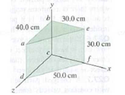
Figure E27.14

Learn your wayIncludes step-by-step video

Chapter 27 Solutions
University Physics with Modern Physics, Books a la Carte Edition (14th Edition)
Additional Science Textbook Solutions
College Physics
Life in the Universe (4th Edition)
The Cosmic Perspective Fundamentals (2nd Edition)
College Physics: A Strategic Approach (4th Edition)
Essential University Physics: Volume 1 (3rd Edition)
Physics for Scientists and Engineers: A Strategic Approach with Modern Physics (4th Edition)


- Assume the region to the right of a certain plane contains a uniform magnetic field of magnitude 1.00 mT and the field is zero in the region to the left of the plane as shown in Figure P22.71. An electron, originally traveling perpendicular to the boundary plane, passes into the region of the field. (a) Determine the time interval required for the electron to leave the field-filled region, noting that the electrons path is a semicircle. (b) Assuming the maximum depth of penetration into the field is 2.00 cm, find the kinetic energy of the electron.arrow_forwardA toroid has a major radius R and a minor radius r and is tightly wound with N turns of wire on a hollow cardboard torus. Figure P31.6 shows half of this toroid, allowing us to see its cross section. If R r, the magnetic field in the region enclosed by the wire is essentially the same as the magnetic field of a solenoid that has been bent into a large circle of radius R. Modeling the field as the uniform field of a long solenoid, show that the inductance of such a toroid is approximately L=120N2r2R Figure P31.6arrow_forwardTwo infinitely long current-carrying wires run parallel in the xy plane and are each a distance d = 11.0 cm from the y axis (Fig. P30.83). The current in both wires is I = 5.00 A in the negative y direction. a. Draw a sketch of the magnetic field pattern in the xz plane due to the two wires. What is the magnitude of the magnetic field due to the two wires b. at the origin and c. as a function of z along the z axis, at x = y = 0? FIGURE P30.83arrow_forward
- Acircularcoiofwireofradius5.Ocmhas2Otums and carries a current of 2.0 A. The coil lies in a magnetic field of magnitude 0.50 T that is directed parallel to the plane of the coil. (a) What is the magnetic dipole moment of the coil? (b) What is the torque on the coil?arrow_forwardA strip of copper is placed in a uniform magnetic field of magnitude 2.5 T. The Hall electric field is measured to be 1.5103V/m (a) What is the drift speed of the conduction electrons? (b) Assuming that n =8.01028 elections per cubic meter and that the cross-sectional area of the strip is 5.0106m2 , calculate the current in the ship, (c) What is the Hall coefficient 1/nq?arrow_forwardA uniform magnetic field B=5.44104iT passes through a closed surface with a slanted top as shown in Figure P31.59. a. Given the dimensions and orientation of the closed surface shown, what is the magnetic flux through the slanted top of the surface? b. What is the net magnetic flux through the entire closed surface?arrow_forward
- A long, straight wire of radius R caries a current I that is distributed uniformly over the cross-section of the wire. At what distance from the axis of the wire is the magnitude of the magnetic field a maximum?arrow_forwardThe Hall effect finds important application in the electronics industry. It is used to find the sign and density of the carriers of electric current in semiconductor chips. The arrangement is shown in Figure P22.66. A semiconducting block of thickness t and width d carries a current I in the x direction. A uniform magnetic field B is applied in the y direction. If the charge carriers are positive, the magnetic force deflects them in the z direction. Positive charge accumulates on the top surface of the sample and negative charge on the bottom surface, creating a downward electric field. In equilibrium, the downward electric force on the charge carriers balances the upward magnetic force and the carriers move through the sample without deflection. The Hall voltage ΔVH = Vc − Va between the top and bottom surfaces is measured, and the density of the charge carriers can be calculated from it. (a) Demonstrate that if the charge carriers are negative the Hall voltage will be negative. Hence, the Hall effect reveals the sign of the charge carriers, so the sample can be classified as p-type (with positive majority charge carriers) or n-type (with negative). (b) Determine the number of charge carriers per unit volume n in terms of I, t, B, ΔVH, and the magnitude q of the carrier charge. Figure P22.66arrow_forwardTwo frictionless conducting rails separated by l = 55.0 cm are connected through a 2.00- resistor, and the circuit is completed by a bar that is free to slide on the rails (Fig. P32.71). A uniform magnetic field of 5.00 T directed out of the page permeates the region, a. What is the magnitude of the force Fp that must be applied so that the bar moves with a constant speed of 1.25 m/s to the right? b. What is the rate at which energy is dissipated through the 2.00- resistor in the circuit?arrow_forward
- Figure P30.10 shows a circular current-carrying wire. Using the coordinate system indicated (with the z axis out of the page), state the direction of the magnetic field at points A and B.arrow_forwardTwo long coaxial copper tubes, each of length L, are connected to a battery of voltage V. The inner tube has inner radius o and outer radius b, and the outer tube has inner radius c and outer radius d. The tubes are then disconnected from the battery and rotated in the same direction at angular speed of radians per second about their common axis. Find the magnetic field (a) at a point inside the space enclosed by the inner tube r d. (Hint: Hunk of copper tubes as a capacitor and find the charge density based on the voltage applied, Q=VC, C=20LIn(c/b) .)arrow_forwardA magnetic field directed into the page changes with time according to B = 0.030 0t2 + 1.40, where B is in teslas and t is in seconds. The field has a circular cross section of radius R = 2.50 cm (see Fig. P23.28). When t = 3.00 s and r2 = 0.020 0 m, what are (a) the magnitude and (b) the direction of the electric field at point P2?arrow_forward
 Physics for Scientists and Engineers: Foundations...PhysicsISBN:9781133939146Author:Katz, Debora M.Publisher:Cengage Learning
 Principles of Physics: A Calculus-Based TextPhysicsISBN:9781133104261Author:Raymond A. Serway, John W. JewettPublisher:Cengage Learning
 Physics for Scientists and Engineers with Modern ...PhysicsISBN:9781337553292Author:Raymond A. Serway, John W. JewettPublisher:Cengage Learning
 Physics for Scientists and EngineersPhysicsISBN:9781337553278Author:Raymond A. Serway, John W. JewettPublisher:Cengage Learning
 Physics for Scientists and Engineers, Technology ...PhysicsISBN:9781305116399Author:Raymond A. Serway, John W. JewettPublisher:Cengage Learning