
Concept explainers
Videos
In Figure P27.7, capacitor 1 (C1 = 20.0 μF) initially has a potential difference of 50.0 V and capacitor 2 (C2 = 5.00 μF) has none. The switches are then closed simultaneously. a. Find the final charge on each capacitor after a long time has passed. b. Calculate the percentage of the initial stored energy that was lost when the switches were closed.
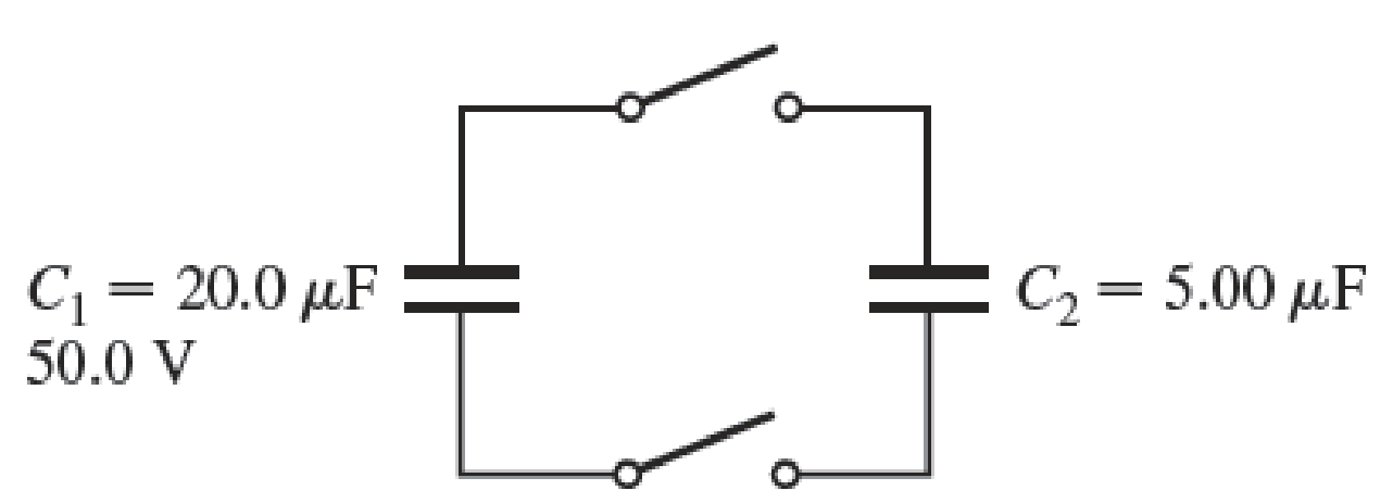
FIGURE P27.7
(a)
The final charge on each capacitor.
Answer to Problem 7PQ
The final charges on each capacitor are
Explanation of Solution
Write the equation for the final charge in capacitor 1.
Here,
Write the equation for the final charge in capacitor 2.
Here,
Write the expression for the equivalent capacitance.
Here,
Write the expression for the new potential difference.
Here,
Write the expression for the initial charge.
Here,
Rewrite the expression for the final charge on capacitor 1.
Rewrite the expression for the final charge on capacitor 2.
Conclusion:
Substitute
Substitute
Thus, the final charges on each capacitor are
(b)
The percentage of the initial stored energy that was lost when the switches were closed.
Answer to Problem 7PQ
The percentage of the initial stored energy that was lost when the switches were closed is
Explanation of Solution
Write the equation for the fraction of loss of energy.
Here,
Write the expression for the initial energy,
Write the expression for the final energy,
Rewrite the expression for the fraction of loss of energy.
Conclusion:
Substitute
Thus, the percentage of the initial stored energy that was lost when the switches were closed is
Want to see more full solutions like this?
Chapter 27 Solutions
Student Solutions Manual For Katz's Physics For Scientists And Engineers: Foundations And Connections, Volume 1


- Figure P27.75 shows four capacitors with CA = 4.00 F, CB = 8.00 F. CC = 6.00 F. and CD = 5.00 F connected across points a and b, which have potential difference Vab = 12.0 V. a. What is the equivalent capacitance of the four capacitors? b. What is the charge on each of the four capacitors?arrow_forwardConsider an infinitely long network with identical capacitors arranged as shown in Figure P27.82. Determine the equivalent capacitance of such a network. Each capacitor has a capacitance of 1.00 F.arrow_forwardA Pairs of parallel wires or coaxial cables are two conductors separated by an insulator, so they have a capacitance. For a given cable, the capacitance is independent of the length if the cable is very long. A typical circuit model of a cable is shown in Figure P27.87. It is called a lumped-parameter model and represents how a unit length of the cable behaves. Find the equivalent capacitance of a. one unit length (Fig. P27.87A), b. two unit lengths (Fig. P27.87B), and c. an infinite number of unit lengths (Fig. P27.87C). Hint: For the infinite number of units, adding one more unit at the beginning does not change the equivalent capacitance.arrow_forward
- A parallel-plate capacitor has square plates of side s = 2.50 cm and plate separation d = 2.50 mm. The capacitor is charged by a battery to a charge Q = 4.00 C, after which the battery is disconnected. A porcelain dielectric ( = 6.5) is then inserted a distance y = 1.00 cm into the capacitor (Fig. P27.88). Hint: Consider the system as two capacitors connected in parallel. a. What is the effective capacitance of this capacitor? b. How much energy is stored in the capacitor? c. What are the magnitude and direction of the force exerted on the dielectric by the plates of the capacitor? Figure P27.88arrow_forwardGiven the arrangement of capacitors in Figure P27.23, find an expression for the equivalent capacitance between points a and b. Figure P27.23 Problems 23 and 24.arrow_forwardThe circuit in Figure P27.85 shows four capacitors connected to a battery. The switch S is initially open, and all capacitors have reached their final charge. The capacitances are C1 = 6.00 F, C2 = 12.00 F, C3 = 8.00 F, and C4 = 4.00 F. a. Find the potential difference across each capacitor and the charge stored in each. b. The switch is now closed. What is the new final potential difference across each capacitor and the new charge stored in each? Figure P27.85arrow_forward
- Consider the combination of capacitors in Figure P16.42. (a) Find the equivalent single capacitance of the two capacitors in series and redraw the diagram (called diagram 1) with this equivalent capacitance. (b) In diagram 1, find the equivalent capacitance of the three capacitors in parallel and redraw the diagram as a single battery and single capacitor in a loop. (c) Compute the charge on the single equivalent capacitor. (d) Returning to diagram 1, compute the charge on each individual capacitor. Does the sum agree with the value found in part (c)? (e) What is the charge on the 24.0-F capacitor and on the 8.00-F capacitor? Compute the voltage drop across (f) the 24.0-F capacitor and (g) the 8.00-F capacitor. Figure P16.42arrow_forwardA charge Q is placed on a capacitor of capacitance C. The capacitor is connected into the circuit shown in Figure P26.37, with an open switch, a resistor, and an initially uncharged capacitor of capacitance 3C. The switch is then closed, and the circuit comes to equilibrium. In terms of Q and C, find (a) the final potential difference between the plates of each capacitor, (b) the charge on each capacitor, and (c) the final energy stored in each capacitor. (d) Find the internal energy appearing in the resistor. Figure P26.37arrow_forwardThree capacitors are connected to a battery as shown in Figure P25.10. Their capacitances are C1 = 3C, C2 = C, and C3 = 5C. (a) What is the equivalent capacitance of this set of capacitors? (b) State the ranking of the capacitors according to the charge they store from largest to smallest. (c) Rank the capacitors according to the potential differences across them from largest to smallest. (d) What If? Assume C3 is increased. Explain what happens to the charge stored by each capacitor. Figure P25.10arrow_forward
- Consider the combination of capacitors in Figure P16.42. (a) Find the equivalent single capacitance of the two capacitors in series and redraw the diagram (called diagram 1) with this equivalent capacitance. (b) In diagram 1, find the equivalent capacitance of the three capacitors in parallel and redraw the diagram as a single battery and single capacitor in a loop. (c) Compute the charge on the single equivalent capacitor. (d) Returning to diagram 1, compute the charge on each individual capacitor. Does the sum agree with the value found in part (c)? (e) What is the charge on the 24.0-F capacitor and on the 8.00-F capacitor? Compute the voltage drop across (f) the 24.0-F capacitor and (g) the 8.00-F capacitor. Figure P16.42arrow_forward(a) Regarding the Earth and a cloud layer 800 m above the Earth as the plates of a capacitor, calculate the capacitance of the Earthcloud layer system. Assume the cloud layer has an area of 1.00 km2 and the air between the cloud and the ground is pure and dry. Assume charge builds up on the cloud and on the ground until a uniform electric field of 3.00 106 N/C throughout the space between them makes the air break down and conduct electricity as a lightning bolt. (b) What is the maximum charge the cloud can hold?arrow_forwardThree capacitors having capacitances 8.4, 8.4, and 4.2 F are connected in series across a 36.0-V potential difference, (a) What is the total energy stored in all three capacitors? (b) The capacitors are disconnected from the potential difference without allowing them to discharge. They are then reconnected in parallel with each other with the positively charged plates connected together. What is the total energy now stored in the capacitors?arrow_forward
 Physics for Scientists and Engineers: Foundations...PhysicsISBN:9781133939146Author:Katz, Debora M.Publisher:Cengage Learning
 Physics for Scientists and Engineers with Modern ...PhysicsISBN:9781337553292Author:Raymond A. Serway, John W. JewettPublisher:Cengage Learning
 Physics for Scientists and EngineersPhysicsISBN:9781337553278Author:Raymond A. Serway, John W. JewettPublisher:Cengage Learning
 Principles of Physics: A Calculus-Based TextPhysicsISBN:9781133104261Author:Raymond A. Serway, John W. JewettPublisher:Cengage Learning
 Physics for Scientists and Engineers, Technology ...PhysicsISBN:9781305116399Author:Raymond A. Serway, John W. JewettPublisher:Cengage Learning