
Videos
(a)
The equivalent resistance of the circuit given.
(a)
Answer to Problem 60AP
The equivalent resistor of the circuit is
Explanation of Solution
Following figure shows the resistance connected a voltage source of
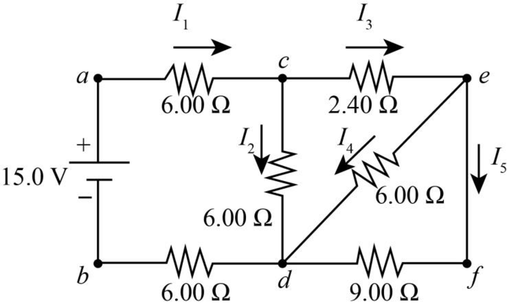
Figure-(1)
Write the expression for equivalent resistance connected in parallel.
Here,
Write the expression for equivalent resistance connected in series.
Here,
Following figure shows the rearranged circuit of the system from Figure (1) for better understanding.
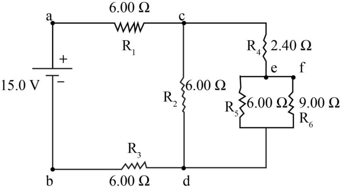
Figure-(2)
Conclusion:
From figure (2) calculate the equivalent resistance for
Substitute
Following figure shows the reduced circuit for the above equivalence.
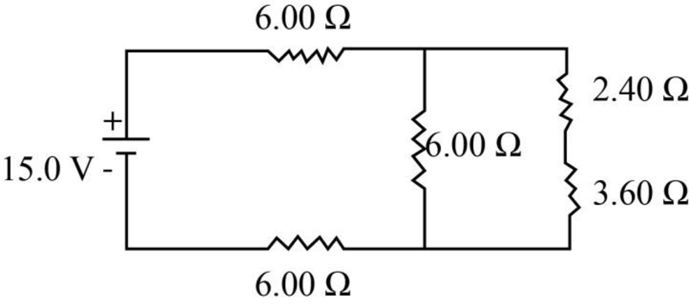
Figure-(3)
From figure (3) calculate the equivalent resistance for
Substitute
Following figure shows the reduced circuit for the above equivalence.
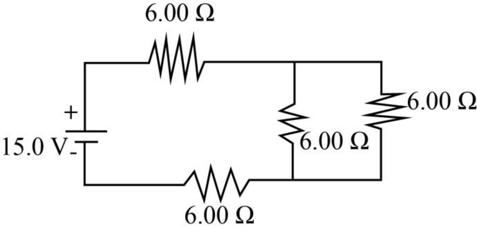
Figure-(4)
From figure (4) calculate the equivalent resistance for
Substitute
Following figure shows the reduced circuit for the above equivalence.
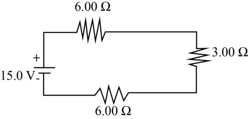
Figure-(5)
From figure (5) calculate the equivalent resistance for
Substitute
Therefore the equivalent resistor for the circuit is
(b)
The potential difference across each resistor.
(b)
Answer to Problem 60AP
voltage between junctions
Explanation of Solution
Write the expression for potential difference between two points of a resistor.
Here,
Conclusion:
Substitute
Calculate voltage drop across each
Substitute
Calculate voltage drop across
Substitute
Calculate current through
Substitute
Calculate voltage drop across
Substitute
Calculate the voltage drop across
Substitute
Therefore, voltage drop across the parallel resistor
Therefore, voltage between junctions
(c)
The each current indicated in the circuit.
(c)
Answer to Problem 60AP
ThecCurrent
Explanation of Solution
Rewrite Equation (III) to calculate
Conclusion:
Substitute
Substitute
Substitute
Substitute
Substitute
Therefore, current
(d)
The power delivered to each resistor.
(d)
Answer to Problem 60AP
Power delivered to resistor
Explanation of Solution
Write the expression for power in resistor.
Here,
Conclusion:
Substitute
Substitute
Substitute
Substitute
Substitute
Substitute
Therefore, power at resistor
Want to see more full solutions like this?
Chapter 28 Solutions
Physics for Scientists and Engineers with Modern Physics Technology Update


- For the circuit shown in Figure P28.55. the ideal voltmeter reads 6.00 V and the ideal ammeter reads 3.00-k. Find (a) the value of K, (b) the emf of the battery, and (c) the voltage across the 3.00-kft resistor.arrow_forwardConsider a series RC circuit as in Figure P28.38 for which R = 1.00 M, C = 5.00 F, and = 30.0 V. Find (a) the time constant of the circuit and (b) the maximum charge on the capacitor after the switch is thrown closed. (c) Find the current in the resistor 10.0 s after the switch is closed.arrow_forwardFigure P29.45 shows five resistors connected between terminals a and b. a. What is the equivalent resistance of this combination of resistors? b. What is the current through each resistor if a 24.0-V battery is connected across the terminals?arrow_forward
- For the network in Figure P18.60, show that the resistance between points a and b is Rab=2717. (Hint: Connect a battery with emf across points a and b and determine /I, where I is the current in the battery.) Figure P18.60arrow_forward(a) Can the circuit shown in Figure P18.29 be reduced to a single resistor connected to the batteries? Explain. (b) Find the magnitude of the current and its direction in each resistor. Figure P18.29arrow_forwardFigure P29.46 shows a circuit with a 12.0-V battery connected to four resistors. How much power is delivered to each resistor?arrow_forward
- A resistor with R1 = 25.0 Ω is connected to a battery that has negligible internal resistance and electrical energy is dissipated by R1 at a rate of 36.0 W. If a second resistor with R2 = 15.0 Ω is connected in series with R1, what is the total rate at which electrical energy is dissipated by the two resistors?arrow_forwardI would like help with (a) - (c). In the figure the ideal batteries have emfs E1 = 16 V and E2 = 11.0 V and the resistors have resistances R1 = 5.3 Ω and R2 = 8.4 Ω. What are (a) the current, the energy dissipation rate in (b) resistor 1 and (c) resistor 2, and the energy transfer rate in (d) battery 1 and (e) battery 2? Is energy being supplied or absorbed by (f) battery 1 and (g) battery 2?arrow_forwardIn (Figure 1), R1R1R_1 = 3.00 ΩΩ, R2R2R_2 = 7.00 ΩΩ, and R3R3R_3 = 4.00 ΩΩ. The battery has negligible internal resistance. The current I2I2 through R2R2 is 3.00 A . What is the emf of the battery? Express your answer with the appropriate units.arrow_forward
- In the figure below, the ideal batteries have emfs ℰ1 = 12 V, ℰ2 = 6.0 V, and the resistors have resistances R1 = 4.0 Ω and R2 = 5.0 Ω. (a) What is the current in the circuit? _________A(b) What is the dissipation rate in resistor 1? _________W(c) What is the dissipation rate in resistor 2? __________W (please show units when you work this out so that I can follow it easier.)arrow_forwardAn ammeter is connected in series to a battery of voltage V_b and a resistor of unknown resistance R_u (Figure 1). The ammeter reads a current I_0. Next, a resistor of unknown resistance R_r is connected in series to the ammeter, and the ammeter's reading drops to I_1. Finally, a second resistor, also of resistance R_r, is connected in series as well. Now the ammeter reads I_2. If I_1/I_0=4/5, find I_2/I_0arrow_forwardIn the figure the ideal batteries have emfs 1 = 13.1 V and 2 = 4.17 V, and the resistances are each 4.02 Ω. What are the (a) magnitude and (b) direction of i1 and the (c) magnitude and (d) direction of i2? (e) Does battery 1 supply or absorb energy, and (f) what is its energy transfer rate? (g) Does battery 2 supply or absorb energy, and (h) what is its energy transfer rate?arrow_forward
 Physics for Scientists and Engineers: Foundations...PhysicsISBN:9781133939146Author:Katz, Debora M.Publisher:Cengage Learning
 Physics for Scientists and Engineers, Technology ...PhysicsISBN:9781305116399Author:Raymond A. Serway, John W. JewettPublisher:Cengage Learning
 College PhysicsPhysicsISBN:9781305952300Author:Raymond A. Serway, Chris VuillePublisher:Cengage Learning
 College PhysicsPhysicsISBN:9781285737027Author:Raymond A. Serway, Chris VuillePublisher:Cengage Learning