Videos
A filter is a circuit designed to pass AC signals in some frequency range and to attenuate others. Common filters include low-pass filters, which allow low-frequency signals to pass but attenuate high frequencies; high-pass filters, which do the opposite; and band-pass filters, which pass a range of frequencies while attenuating signals with frequencies outside the band. Filters are widely used in electronics. Applications include tone and equalizer controls in audio equipment; filters to separate nearby frequencies at cell phone towers; and filters to eliminate unwanted electrical noise in biomedical instruments such as electrocardiographs. A simple design for an RC filter is shown in Fig. 28.27.
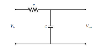
Figure 28.27 An RC filter (Passage Problems 73–76)
If you replace the capacitor in Fig. 28.27 with an inductor, the circuit
- a. continues to function as before.
- b. becomes the opposite kind of filter.
- c. produces zero output voltage because the inductor is a short circuit.
- d. produces an output voltage that exceeds the input voltage.
Want to see the full answer?
Check out a sample textbook solution
Chapter 28 Solutions
Essential University Physics -Modified MasteringPhysics Access
Additional Science Textbook Solutions
Physics: Principles with Applications
College Physics
Essential University Physics: Volume 1 (3rd Edition)
University Physics Volume 1
Conceptual Integrated Science
University Physics with Modern Physics (14th Edition)


- The emf of an ac source is given by v(t)=V0sint, where V0=100V and =200 . Find an expression that represents the output current of the source if it is connected across (a) a 20-pF capacitor, (b) a 20-mH inductor, and (c) a 50 resistor.arrow_forwardA 1.5k resistor and 30-mH inductor are connected in series, as below, across a120-V(rms)ac power source oscillating at 60-Hz frequency. (a) Find the current in the circuit. (b) Find the voltage drops across the resistor and inductor. (C) Find the impedance of the circuit. (d) Find the power dissipated in the resistor. (e) Find the power dissipated in the inductor. (1) Find the power produced by the source.arrow_forwardReview. The voltage phasor diagram for a certain series RLC circuit is shown in Figure P33.59. The resistance of the circuit is 75.0 , and the frequency is 60.0 Hz. Find (a) the maximum voltage Vmax, (b) the phase angle , (c) the maximum current, (d) the impedance, (e) the capacitance and (f) the inductance of the circuit, and (g) the average power delivered to the circuit.arrow_forward
- In the AC circuit shown in Figure P32.3, R = 70.0 and the output voltage of the AC source is Vmax sin t. (a) If VR = 0.250 Vmax for the first time at t = 0.0100 s, what is the angular frequency of the source? (b) What is the next value of t for which VR = 0.250 Vmax? Figure P32.6 Problem 3 and 5.arrow_forwardIn a purely inductive AC circuit as shown in Figure P32.6, Vmax = 100 V. (a) The maximum current is 7.50 A at 50.0 Hz. Calculate the inductance L. (b) What If? At what angular frequency is the maximum current 2.50 A? Figure P32.6 Problem 6 and 7.arrow_forwardAn ac source of voltage amplitude 10 V delivers electric energy at a rate of 0.80 W when its current output is 2.5 A. What is the phase angle between the emf and the current?arrow_forward
- The resistor in Figure P32.49 represents the midrange speaker in a three-speaker system. Assume its resistance to be constant at 8.00 . The source represents an audio amplifier producing signals of uniform amplitude Vmax = 10.0 V at all audio frequencies. The inductor and capacitor are to function as a band-pass filter with Vout/Vin=12 at 200 Hz and at 4.00 103 Hz. Determine the required values of (a) L and (b) C. Find (c) the maximum value of the ratio Vout/Vin; (d) the frequency fo at which the ratio has its maximum value; (e) the phase shift between vin and vout at 200 Hz, at fo, and at 4.00 103 Hz; and (f) the average power transferred to the speaker at 200 Hz, at f0, and at 4.00 103 Hz. (g) Recognizing that the diagram represents an RLC circuit driven by an AC source, find its quality factor. Figure P32.49arrow_forwardA series RLC circuit has resistance R = 50.0 and inductance L. = 0.500 H. (a) Find the circuits capacitance C if the voltage source operates at a frequency of f = 60.0 Hz and the impedance is Z = R = 50.0 . (b) What is the phase angle between the current and the voltage?arrow_forwardAn inductor and a resistor are connected in series across an AC generator, as shown in Figure CQ21.16. Immediately after the switch is closed, which of the following statements is true? (a) The current is V/R. (b) The voltage across the inductor is zero. (c) The current in the circuit is zero. (d) The voltage across the resistor is V. (e) The voltage across the inductor is half its maximum value. Figure CQ21.16arrow_forward
 Physics for Scientists and EngineersPhysicsISBN:9781337553278Author:Raymond A. Serway, John W. JewettPublisher:Cengage Learning
 Physics for Scientists and Engineers with Modern ...PhysicsISBN:9781337553292Author:Raymond A. Serway, John W. JewettPublisher:Cengage Learning
 Physics for Scientists and Engineers, Technology ...PhysicsISBN:9781305116399Author:Raymond A. Serway, John W. JewettPublisher:Cengage Learning
 Physics for Scientists and Engineers: Foundations...PhysicsISBN:9781133939146Author:Katz, Debora M.Publisher:Cengage Learning
 College PhysicsPhysicsISBN:9781305952300Author:Raymond A. Serway, Chris VuillePublisher:Cengage Learning