
Concept explainers
Videos
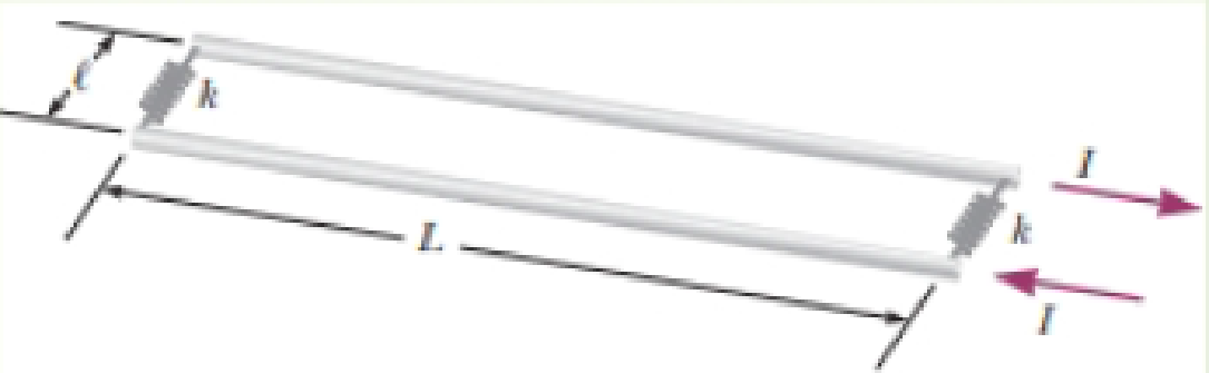
You are part of a team working in a machine parts mechanic’s shop. An important customer has asked your company to provide springs with a very precise force constant k. To measure the spring constant, you fasten two of the springs between the ends of two very long wires of length L, separated by the unstretched length ℓ of the springs as shown in Figure P29.15. The specific attachment method that you use insulates the springs from the wires so that no current passes through the springs. You lay the apparatus flat on a table and then pass a current of magnitude I through the wires, in opposite directions. As a result the springs stretch by a distance d and come to equilibrium. You determine an expression for the spring constant in terms of L, I, ℓ, and d.
Figure P29.15
Want to see the full answer?
Check out a sample textbook solution
Chapter 29 Solutions
Physics for Scientists and Engineers with Modern Physics
Additional Science Textbook Solutions
College Physics: A Strategic Approach (3rd Edition)
Essential University Physics: Volume 2 (3rd Edition)
Integrated Science
The Physics of Everyday Phenomena
Loose Leaf For Explorations: Introduction To Astronomy
Physics for Scientists and Engineers, Technology Update (No access codes included)


- Figure P30.10 shows a circular current-carrying wire. Using the coordinate system indicated (with the z axis out of the page), state the direction of the magnetic field at points A and B.arrow_forwardReview. In studies of the possibility of migrating birds using the Earths magnetic field for navigation, birds have been fitted with coils as caps and collars as shown in Figure P22.39. (a) If the identical coils have radii of 1.20 cm and are 2.20 cm apart, with 50 turns of wire apiece, what current should they both carry to produce a magnetic field of 4.50 105 T halfway between them? (b) If the resistance of each coil is 210 V, what voltage should the battery supplying each coil have? (c) What power is delivered to each coil? Figure P22.39arrow_forwardReview. Rail guns have been suggested for launching projectiles into space without chemical rockets. A tabletop model rail gun (Fig. P22.76) consists of two long, parallel, horizontal rails = 3.50 cm apart, bridged by a bar of mass m = 3.00 g that is free to slide without friction. The rails and bar have low electric resistance, and the current is limited to a constant I = 24.0 A by a power supply that is far to the left of the figure, so it has no magnetic effect on the bar. Figure P22.76 shows the bar at rest at the midpoint of the rails at the moment the current is established. We wish to find the speed with which the bar leaves the rails after being released from the midpoint of the rails. (a) Find the magnitude of the magnetic field at a distance of 1.75 cm from a single long wire carrying a current of 2.40 A. (b) For purposes of evaluating the magnetic field, model the rails as infinitely long. Using the result of part (a), find the magnitude and direction of the magnetic field at the midpoint of the bar. (c) Argue that this value of the field will be the same at all positions of the bar to the right of the midpoint of the rails. At other points along the bar, the field is in the same direction as at the midpoint, but is larger in magnitude. Assume the average effective magnetic field along the bar is five times larger than the field at the midpoint. With this assumption, find (d) the magnitude and (e) the direction of the force on the bar. (f) Is the bar properly modeled as a particle under constant acceleration? (g) Find the velocity of the bar after it has traveled a distance d = 130 cm to the end of the rails. Figure P22.76arrow_forward
- A piece of insulated wire is shaped into a figure eight as shown in Figure P23.12. For simplicity, model the two halves of the figure eight as circles. The radius of the upper circle is 5.00 cm and that of the lower circle is 9.00 cm. The wire has a uniform resistance per unit length of 3.00 Ω/m. A uniform magnetic field is applied perpendicular to the plane of the two circles, in the direction shown. The magnetic field is increasing at a constant rate of 2.00 T/s. Find (a) the magnitude and (b) the direction of the induced current in the wire. Figure P23.12arrow_forwardThe Hall effect finds important application in the electronics industry. It is used to find the sign and density of the carriers of electric current in semiconductor chips. The arrangement is shown in Figure P22.66. A semiconducting block of thickness t and width d carries a current I in the x direction. A uniform magnetic field B is applied in the y direction. If the charge carriers are positive, the magnetic force deflects them in the z direction. Positive charge accumulates on the top surface of the sample and negative charge on the bottom surface, creating a downward electric field. In equilibrium, the downward electric force on the charge carriers balances the upward magnetic force and the carriers move through the sample without deflection. The Hall voltage ΔVH = Vc − Va between the top and bottom surfaces is measured, and the density of the charge carriers can be calculated from it. (a) Demonstrate that if the charge carriers are negative the Hall voltage will be negative. Hence, the Hall effect reveals the sign of the charge carriers, so the sample can be classified as p-type (with positive majority charge carriers) or n-type (with negative). (b) Determine the number of charge carriers per unit volume n in terms of I, t, B, ΔVH, and the magnitude q of the carrier charge. Figure P22.66arrow_forwardUnreasonable results Frustrated by the small Hall voltage obtained in blood flow measurements, a medical physicist decides to increase the applied magnetic field strength to get a 0.500-V output for blood moving at 30.0 cm/s in a 1.50-cm-diameter vessel. (a) What magnetic field strength is needed? (b) What is unreasonable about this result? (C) Which premise is responsible?arrow_forward
- A circular coil 15.0 cm in radius and composed of 145 tightly wound turns carries a current of 2.50 A in the counterclockwise direction, where the plane of the coil makes an angle of 15.0 with the y axis (Fig. P30.73). The coil is free to rotate about the z axis and is placed in a region with a uniform magnetic field given by B=1.35jT. a. What is the magnitude of the magnetic torque on the coil? b. In what direction will the coil rotate? FIGURE P30.73arrow_forwardConsider the system pictured in Figure P28.26. A 15.0-cm horizontal wire of mass 15.0 g is placed between two thin, vertical conductors, and a uniform magnetic field acts perpendicular to the page. The wire is free to move vertically without friction on the two vertical conductors. When a 5.00-A current is directed as shown in the figure, the horizontal wire moves upward at constant velocity in the presence of gravity. (a) What forces act on the horizontal wire, and (b) under what condition is the wire able to move upward at constant velocity? (c) Find the magnitude and direction of the minimum magnetic Field required to move the wire at constant speed. (d) What happens if the magnetic field exceeds this minimum value? Figure P28.26arrow_forward
 Physics for Scientists and Engineers with Modern ...PhysicsISBN:9781337553292Author:Raymond A. Serway, John W. JewettPublisher:Cengage Learning
 Physics for Scientists and EngineersPhysicsISBN:9781337553278Author:Raymond A. Serway, John W. JewettPublisher:Cengage Learning
 Physics for Scientists and Engineers: Foundations...PhysicsISBN:9781133939146Author:Katz, Debora M.Publisher:Cengage Learning
 Principles of Physics: A Calculus-Based TextPhysicsISBN:9781133104261Author:Raymond A. Serway, John W. JewettPublisher:Cengage Learning
 Physics for Scientists and Engineers, Technology ...PhysicsISBN:9781305116399Author:Raymond A. Serway, John W. JewettPublisher:Cengage Learning