Videos
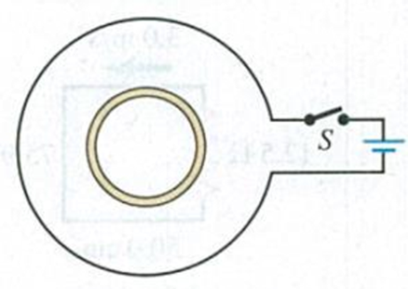
A small, circular ring is inside a larger loop that is connected to a battery and a switch (Fig. E29.21). Use Lenz’s law to find the direction of the current induced in the small ring (a) just after switch S is closed; (b) after S has been closed a long time; (c) just after S has been reopened after it was closed for a long time.
Figure E29.21

Learn your wayIncludes step-by-step video

Chapter 29 Solutions
University Physics with Modern Physics, Volume 2 (Chs. 21-37); Mastering Physics with Pearson eText -- ValuePack Access Card (14th Edition)
Additional Science Textbook Solutions
University Physics (14th Edition)
Physics for Scientists and Engineers with Modern Physics
Essential University Physics: Volume 1 (3rd Edition)
Essential University Physics: Volume 2 (3rd Edition)
Conceptual Physics (12th Edition)
Life in the Universe (4th Edition)


- A rectangular conducting loop is placed near a long wire carrying a current I as shown in Figure OQ23.5. If I decreases in time, what can be said of the current induced in the loop? (a) The direction of the current depends on the size of the loop. (b) The current is clockwise. (c) The current is counterclockwise. (d) The current is zero. (e) Nothing can be said about the current in the loop without more information.arrow_forwardIn Figure P20.65 the rolling axle of length 1.50 m is pushed along horizontal rails at a constant speed v = 3.00 m/s. A resist or R = 0.400 is connected to the rails at points a and b, directly opposite each other. (The wheels make good electrical contact with the rails, so the axle, rails, and R form a closed-loop circuit. The only significant resistance in the circuit is R.) A uniform magnetic field B = 0.800 T is directed vertically downward. (a) Find the induced current I in the resistor. (b) What horizontal force F is required to keep the axle rolling at constant speed? (c) Which end of the resistor, a or b. is at the higher electric potential? (d) Alter the axle rolls past the resistor, does the current in R reverse direction? Explain your answer. Figure P20.65arrow_forwardFigure P23.58 is a graph of the induced emf versus time for a coil of N turns rotating with angular speed ω in a uniform magnetic field directed perpendicular to the coil’s axis of rotation. What If? Copy this sketch (on a larger scale) and on the same set of axes show the graph of emf versus t (a) if the number of turns in the coil is doubled, (b) if instead the angular speed is doubled, and (c) if the angular speed is doubled while the number of turns in the coil is halved. Figure P23.58arrow_forward
- A square, flat loop of wire is pulled at constant velocity through a region of uniform magnetic field directed perpendicular to the plane of the loop as shown in Figure OQ23.9. Which of the following statements are correct? More than one statement may be correct. (a) Current is induced in the loop in the clockwise direction. (b) Current is induced in the loop in the counterclockwise direction. (c) No current is induced in the loop. (d) Charge separation occurs in the loop, with the top edge positive. (e) Charge separation occurs in the loop, with the top edge negative.arrow_forwardA stiff spring with a spring constant of 1200.0 N/m is connected to a bar on a slide generator as shown in Figure P32.40. Assume the bar has length l = 60.0 cm and mass m = 0.75 kg, and it slides without friction. The bar connects to a U-shaped wire to form a loop that has width w = 40.0 cm and total resistance 25 and that sits in a uniform magnetic field B = 0.35 T. The bar is initially pulled 5.0 cm to the left and released so that it begins to oscillate. What is the induced current in the loop as a function of time, I(t)? (Ignore any effects due to the magnetic force on the oscillating bar.)arrow_forwardA piece of insulated wire is shaped into a figure eight as shown in Figure P23.12. For simplicity, model the two halves of the figure eight as circles. The radius of the upper circle is 5.00 cm and that of the lower circle is 9.00 cm. The wire has a uniform resistance per unit length of 3.00 Ω/m. A uniform magnetic field is applied perpendicular to the plane of the two circles, in the direction shown. The magnetic field is increasing at a constant rate of 2.00 T/s. Find (a) the magnitude and (b) the direction of the induced current in the wire. Figure P23.12arrow_forward
- A circular loop of wire with a radius of 4.0 cm is in a uniform magnetic field of magnitude 0.060 T. The plane of the loop is perpendicular to the direction of the magnetic field. In a time interval of 0.50 s, the magnetic field changes to the opposite direction with a magnitude of 0.040 T. What is the magnitude of the average emf induced in the loop? (a) 0.20 V (b) 0.025 V (c) 5.0 mV (d) 1.0 mV (e) 0.20 mVarrow_forwardReview. Figure P31.31 shows a bar of mass m = 0.200 kg that can slide without friction on a pair of rails separated by a distance = 1.20 m and located on an inclined plane that makes an angle = 25.0 with respect to the ground. The resistance of the resistor is R = 1.00 and a uniform magnetic field of magnitude B = 0.500 T is directed downward, perpendicular to the ground, over the entire region through which the bar moves. With what constant speed v does the bar slide along the rails?arrow_forwardFigure P30.39 shows a stationary conductor whose shape is similar to the letter e. The radius of its circular portion is a = 50.0 cm. It is placed in a constant magnetic field of 0.500 T directed out of the page. A straight conducting rod, 50.0 cm long, is pivoted about point O and rotates with a constant angular speed of 2.00 rad/s. (a) Determine the induced emf in the loop POQ. Note that the area of the loop is a2/2. (b) If all the conducting material has a resistance per length of 5.00 /m, what is the induced current in the loop POQ at the instant 0.250 s after point P passes point Q? Figure P30.39arrow_forward
 Principles of Physics: A Calculus-Based TextPhysicsISBN:9781133104261Author:Raymond A. Serway, John W. JewettPublisher:Cengage Learning
 Physics for Scientists and Engineers: Foundations...PhysicsISBN:9781133939146Author:Katz, Debora M.Publisher:Cengage Learning
 Physics for Scientists and Engineers with Modern ...PhysicsISBN:9781337553292Author:Raymond A. Serway, John W. JewettPublisher:Cengage Learning
 Physics for Scientists and EngineersPhysicsISBN:9781337553278Author:Raymond A. Serway, John W. JewettPublisher:Cengage Learning
 Physics for Scientists and Engineers, Technology ...PhysicsISBN:9781305116399Author:Raymond A. Serway, John W. JewettPublisher:Cengage Learning
 College PhysicsPhysicsISBN:9781285737027Author:Raymond A. Serway, Chris VuillePublisher:Cengage Learning