
Concept explainers
Videos
The missing values in the given table.
Answer to Problem 4PP
| Primary | Secondary | Load |
| EP = 23000 V | EP = 120 V | EP = 208 V |
| IP = 0.626A | IP = 120.08 A | IP = 69.33 A |
| EL = 23000 V | EL = 208 V | EL = 208 V |
| IL = 1.084 A | IL = 120.08 A | IL = 120.08 A |
| Ratio = 191.52:1 | Z = 3 Ω |
Explanation of Solution
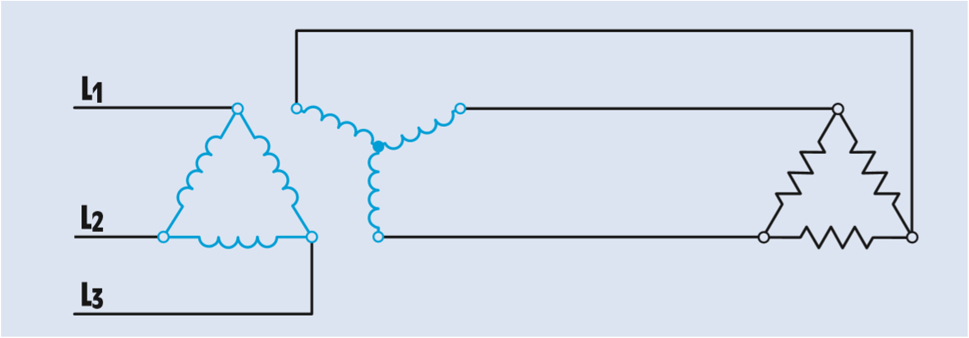
In the figure, three single-phase transformers have been connected to form a delta–wye bank.
The primary is connected to a three-phase line of 23000 V.
The secondary voltage is 208 V.
A three-phase resistive load with an impedance of 3 Ω per phase is connected to the secondary of the transformer.
The primary windings of the three single-phase transformers are connected to form a delta connection. In a delta connection, the phase voltage is equal to line voltage.
The secondary windings are connected as a wye. In a wye connection, the phase voltage is less than the line voltage by a factor of 1.732 (the square root of 3). Therefore, the phase value of the primary voltage can be calculated using the formula
The turns ratio can be calculated by comparing the phase voltage of the primary with the phase voltage of the secondary:
The load is connected directly to the output of the secondary. The line voltage applied to the load must therefore be the same as the line voltage of the secondary:
The load bank is connected in a delta connection. The voltage across the phase of the load bank will equal to the line voltage.
The phase current of the load can be calculated using Ohm’s law:
The amount of line current supplying a delta-connected load will be 1.732 times the phase current of the load:
Since the secondary of the transformer is supplying current to only one load, the line current of the secondary will be the same as the line current of the load:
The phase current in a wye connection is equal to the line current.
The phase current of the transformer primary can now be calculated using the phase current of the secondary and the turns ratio. Because the primary has a higher voltage than the secondary, it will have a lower current. (Volts times amperes input must equal volts times amperes output.)
All the transformed values of voltage and current take place across the phases, the primary has a phase current of 6.68 A. In a delta connection, the line current is 1.732 times the phase current:
Want to see more full solutions like this?
Chapter 29 Solutions
DELMAR'S STANDARD TEXT OF ELECTRICITY


- DETERMINE IF THE STATEMENT/IMAGE IS FOR : DELTA- DELTA or WYE- WYE (follow the writing and spelling as it is) Question: What is the connection of this transformer bank? Note: answer must be all caps with - in between XI | x2 | xoarrow_forward15. Primary winding of transformer is made-up of __________________________ material. a. insulated copper conductor b. Cold Rolled Grain Oriented (CRGO) conductor c. Cold Rolled Grain Oriented (CRGO) Silicon Steel d. insulated CRGO conductorarrow_forwardRefer to the transformer shown in Figure 5-13 to answer the following questions. Assume that a voltage of 208 volts is applied across terminals B and E. How much voltage is across each of the following terminals? A–B ____ A–C ____ A–D ____ A–E ____ B–C ____ B–D ____B–E ____ C–D ____ C–E ____ D–E ____ 2.Assume a voltage of 120 volts is connected across terminals B and E, and that a load impedance of 20 V is connected across terminals A and C. What is the secondary and primary current? IP ____ IS ____ 3.What is the turns ratio of the winding between points B and E as compared to the winding between points D and E? 4.Assume that a voltage of 480 volts is connected across terminals A and E. What is the voltage across terminals C and D? 5.The transformer shown in Figure 5-13 is supplying 325-volt amperes to a load. The primary voltage is 240 volts. What is the primary current?arrow_forward
- h.1. In an alternating-current system, the maximum size for a copper grounding electrode conductor isA. 250 kcmil.B. 3/0.C. 500 kcmil.D. 4/0. h.2. The figure shows a fault condition in an ungrounded electrical system. Which of the following will occurbecause of the fault in this system?A. Only the overcurrent protector at Point A will trip open.B. The ground fault will heavily damage the service.C. Nothing will happen until a second ground fault occurs.D. The overcurrent protection will trip, shutting off all the line side power.arrow_forwardSeconday winding of transformer is made-up of __________________________ material. insulated copper conductor Cold Rolled Grain Oriented (CRGO) Silicon Steel insulated CRGO conductor Cold Rolled Grain Oriented (CRGO) conductorarrow_forwardFill in the blanks with a suitable describing for the following 1. Active component of no load current of transformer is _____________ 2. The resistance of series field windings is __________ and it's have ____________ number of turns 3. Leakage flux of transformer is ___________ 4. Starting torque is __________ in D.C. series motor 5. PID controller is _________arrow_forward
- In a typical unit substation the majority of the connections to ground are made in the_. A. High- voltage section B. Transformer section C. low- voltage section D. None of the above.arrow_forward- Transformers and Special Locations 7.a. Dry-type transformers are available in what configuration(s)?A. Single-phase or auto-phaseB. Poly-phase onlyC. Single- or poly-phaseD. Single-phase only7.b. How many separate and distinct electrical systems does an essential electrical system consist of?A. FiveB. ThreeC. FourD. Sixarrow_forwardLOCAL 5652 UNION LABEL USW UNITED STEELWORKERS 6. Which one of the following types of construction is used for potential transformers? A. Window-type B. Wound-type C. Bushing-type D. Bar-typearrow_forward
- 2. Two different transformers details are tabulated below. Calculate the missed values in the table. Secondary terminal voltage of the second transformer is 487.5V when loaded. Determine the regulation of the transformer. N, | N2 V: 1 1 Transformer V, Flux Area L(60000 VA SOHZ) ? 100 100v ? ? 25cm 1.6KV II.(6000VA 50HZ 100 100 500 ? 0.04505Wb flux density 1.50T)arrow_forwardA fault occurs at point F of the system in the figure. Calculate the sub-transient current in phase c of machine 1, assuming that the currents before the fault are zero. Both machines have a nominal capacity of 1200 kVA, 480 V, with reactances X”=X2= 11% and X0 = 3.5%. The nominal capacity of each three-phase transformer is 1200 kVA, 480 V Δ/ 2400 V and with reactances X1=X2=X0= 6%. Transmission line reactances are X1=X2=22% and X0 = 35% on a 1200 kVA, 2400 V basis. Neutral grounding reactor reactances are 8% on a kVA and kV basis. of the machines. a) Calculate the fault current if a ground fault occurs in phase a, b) The fault current if it is a line-to-line fault c) the voltage in phase b and c for the line-to-ground fault in phase a .arrow_forwardA. Discuss the arcing phenomenon in a circuit breaker. B. Discuss the types of oil circuit breakers. With referencesarrow_forward
 Introductory Circuit Analysis (13th Edition)Electrical EngineeringISBN:9780133923605Author:Robert L. BoylestadPublisher:PEARSON
 Delmar's Standard Textbook Of ElectricityElectrical EngineeringISBN:9781337900348Author:Stephen L. HermanPublisher:Cengage Learning
 Programmable Logic ControllersElectrical EngineeringISBN:9780073373843Author:Frank D. PetruzellaPublisher:McGraw-Hill Education
 Fundamentals of Electric CircuitsElectrical EngineeringISBN:9780078028229Author:Charles K Alexander, Matthew SadikuPublisher:McGraw-Hill Education
 Electric Circuits. (11th Edition)Electrical EngineeringISBN:9780134746968Author:James W. Nilsson, Susan RiedelPublisher:PEARSON
 Engineering ElectromagneticsElectrical EngineeringISBN:9780078028151Author:Hayt, William H. (william Hart), Jr, BUCK, John A.Publisher:Mcgraw-hill Education,