
CONTROL SYSTEMS ENGINEERING - WILEYPLUS
7th Edition
ISBN: 9781119143277
Author: NISE
Publisher: WILEY
expand_more
expand_more
format_list_bulleted
Concept explainers
Videos
Textbook Question
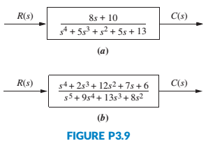
Chapter 3, Problem 11P
For each system shown in Figure P3.9, write the state equations and the output equation for the phase-variable representation. [Section: 3.5]
Expert Solution & Answer
Want to see the full answer?
Check out a sample textbook solution
Students have asked these similar questions
For the following state-space representation,define the:– State Vector– System Matrix– Feedforward Matrix– Input Matrix & Input Vector– Output Matrix & Output Vector
Explain the state space function
does such a decomposition end up using more bandwidth. (This is an exa
Consider the mechanical system shown in the figure below. Suppose the system input u is the velocity d₁,
its output y is the velocity d2, and its states ar are the position d2 and velocity d2. Obtain a state-space
model of the form i = Ar + Bu and y = Cr + Du describing the system.
d₂
d₁
b
m
k₂
Chapter 3 Solutions
CONTROL SYSTEMS ENGINEERING - WILEYPLUS
Ch. 3 - Prob. 1RQCh. 3 - State an advantage of the transfer function...Ch. 3 - Define state variables.Ch. 3 - Define state.Ch. 3 - Define state vector.Ch. 3 - Define state space.Ch. 3 - What is required to represent a system in state...Ch. 3 - 8. An eighth-order system would be represented in...Ch. 3 - If the state equations are a system of first-order...Ch. 3 - Prob. 10RQ
Ch. 3 - What factors influence the choice of state...Ch. 3 - What is a convenient choice of state variables for...Ch. 3 - If an electrical network has three energy-storage...Ch. 3 - Prob. 14RQCh. 3 - Prob. 1PCh. 3 - Represent the electrical network shown in Figure...Ch. 3 - Prob. 3PCh. 3 - Represent the system shown in Figure P3.4 in state...Ch. 3 - Represent the rotational mechanical system shown...Ch. 3 - Represent the system shown in Figure P3.7 in state...Ch. 3 - 8. Show that the system of Figure 3.7 in the text...Ch. 3 - Find the state-space representation in...Ch. 3 - MATLAB ML 10. Repeat Problem 9 using MATLAB....Ch. 3 - For each system shown in Figure P3.9, write the...Ch. 3 - MATLAB ML
12. Repeat Problem 11 using MATLAB....Ch. 3 - 13. Represent the following transfer function in...Ch. 3 - Find the transfer function G(s) = Y(s)/R(s) for...Ch. 3 - MATLAB ML
15. Use MATLAB to find the transfer...Ch. 3 - 17. A missile in flight, as shown in Figure P3.10,...Ch. 3 - Given the dc servomotor and load shown in Figure...Ch. 3 - Prob. 20PCh. 3 - Prob. 23PCh. 3 - Experiments to identify precision grip dynamics...Ch. 3 - State-space representations are, in general, not...Ch. 3 - Figure P3.16 shows a schematic description of the...Ch. 3 - Prob. 28PCh. 3 - A single-pole oil cylinder valve contains a spool...Ch. 3 - Figure P3.17 shows a free-body diagram of an...Ch. 3 - 33. Parabolic trough collector. A transfer...
Knowledge Booster


Learn more about
Need a deep-dive on the concept behind this application? Look no further. Learn more about this topic, mechanical-engineering and related others by exploring similar questions and additional content below.Similar questions
- equations: QB: Obtain the transfer function of system defined by the following state space Hi 0 4 8 [x₁ 0 8 5 X2 + -10-30-20x330/u [123] [x1 Y=[1 2 0] X₂ X3 snp-you tvavearrow_forwardPlease solve the following question. Note that the second picture is the solution of the question from the book, I just want to know the steps to reach it.arrow_forwardPlease solve this for me! Thanks!arrow_forward
- 38. Given the rotational system shown in Figure P2.24, find the transfer function, G(s) = 06(s)/01(s). [Section: 2.7]arrow_forwardPlease answer in typing format Please answer in typing format Please answer in typing format pleasearrow_forwardPlease help me doing part B all I need help with is too make the derivation of equations of motion, and derivation of the state equations, and that will do for part B if you could help me with this it would make my life alot easier, and no matlab is not necessary for this.arrow_forward
- LESSON is Transfer Function: Mechanical System - Rotational Movement SUBJECT: FEEDBACK CONTROL SYSTEM Box the final answerarrow_forwardQ2 In the rotating system shown in Figure Q2. The torque T applied to the rotor and generate the output angular velocity, w. (a) Determine equations of motion system interm of angular displacement, 0. (b) By referring Q2(a), determine the state-space model of the system. Rotor T Figure Q2arrow_forwardMechanics of machines QUESTION 4 Consider two degree of freedom of coupled pendulum with horizontal rod vibration system are shown in figure 4. MA KG. oooo MB BAW a Figure 4 k d L 4.1- Determine differential equations of motion in matrix form using The equation of equation with, and ß as generalized coordinates; 4.2- Develop state-space model.arrow_forward
- Consider the following state space system 1 B = 1 C =[1 0] D=[0] -5 -6 1- Check the controllability of the system. 2- Check the observability of the systemarrow_forwardObtain the state space model of the system shown below. Use equations for control theory state space modeling.arrow_forwardDerive the state-space model (state equation and output equation) in vector form for the following system. The system outputs are the displacements of each spring. Assume that the connection between the spring and rope is massless and that the rope is inextensible. Assume that gravity is an input as well as the applied forces Fi(t) and F2(t). Neglect friction forces on mass m₂. If q₁ is the state variable for the bottom spring connected to m₁, q2 is the state variable for the mass m₁, q3 is the the top spring connected to the pulley, and q4 is the state variable connected to the mass m2, then you should expect to get the following state-space representation: 92 43 y 0 LaLa (L+L) 0 4₂ kL₂ mi Li 0 m2 0 13 (L+L) 0 CA = - [8] 92 93 + 92 93 + L94 m₂ F₂(t) m₂ TOL F₂(t) Figure 2: Diagram for problem 2 X5 00 X2 [000] 00 U₁ U12 U13 m₂. 21 142 143arrow_forward
arrow_back_ios
SEE MORE QUESTIONS
arrow_forward_ios
Recommended textbooks for you
 Elements Of ElectromagneticsMechanical EngineeringISBN:9780190698614Author:Sadiku, Matthew N. O.Publisher:Oxford University Press
 Mechanics of Materials (10th Edition)Mechanical EngineeringISBN:9780134319650Author:Russell C. HibbelerPublisher:PEARSON
 Thermodynamics: An Engineering ApproachMechanical EngineeringISBN:9781259822674Author:Yunus A. Cengel Dr., Michael A. BolesPublisher:McGraw-Hill Education
 Control Systems EngineeringMechanical EngineeringISBN:9781118170519Author:Norman S. NisePublisher:WILEY
 Mechanics of Materials (MindTap Course List)Mechanical EngineeringISBN:9781337093347Author:Barry J. Goodno, James M. GerePublisher:Cengage Learning
 Engineering Mechanics: StaticsMechanical EngineeringISBN:9781118807330Author:James L. Meriam, L. G. Kraige, J. N. BoltonPublisher:WILEY
Elements Of Electromagnetics
Mechanical Engineering
ISBN:9780190698614
Author:Sadiku, Matthew N. O.
Publisher:Oxford University Press
Mechanics of Materials (10th Edition)
Mechanical Engineering
ISBN:9780134319650
Author:Russell C. Hibbeler
Publisher:PEARSON
Thermodynamics: An Engineering Approach
Mechanical Engineering
ISBN:9781259822674
Author:Yunus A. Cengel Dr., Michael A. Boles
Publisher:McGraw-Hill Education
Control Systems Engineering
Mechanical Engineering
ISBN:9781118170519
Author:Norman S. Nise
Publisher:WILEY
Mechanics of Materials (MindTap Course List)
Mechanical Engineering
ISBN:9781337093347
Author:Barry J. Goodno, James M. Gere
Publisher:Cengage Learning
Engineering Mechanics: Statics
Mechanical Engineering
ISBN:9781118807330
Author:James L. Meriam, L. G. Kraige, J. N. Bolton
Publisher:WILEY
Introduction to Kinematics; Author: LearnChemE;https://www.youtube.com/watch?v=bV0XPz-mg2s;License: Standard youtube license