
Introduction To Computing Systems
3rd Edition
ISBN: 9781260150537
Author: PATT, Yale N., Patel, Sanjay J.
Publisher: Mcgraw-hill,
expand_more
expand_more
format_list_bulleted
Videos
Question
Chapter 3, Problem 24E
a.
Program Plan Intro
NOT operation:
- NOT function needs one input and produces one output.
- It is also known as unary logical function.
- Another name of NOT operation is complementary operation.
- Output is produced by complementing the input.
- The following diagram depicts the NOT operation,
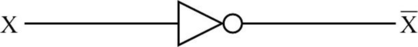
- The NOT operation produces the output “1”, when the source input is “0”.
- The NOT operation produces the output “0”, when the source input is “1”.
- The truth table for the NOT operation is as follows,
| X | |
| 0 | 1 |
| 1 | 0 |
- In the above table, “X” is the input, and “Z” is the output.
- When “X=0”, the output “Z” is the complement of “0”, which means “1” and When “X=1”,the output “Z” is the complement of “1”, which means “0”.
OR operation:
- OR function needs two inputs and produces one output.
- It is also known as binary logical function.
- If one of the inputs or both the inputs are “1”, then one-bit OR operation produces the output as “1”.
- If both the inputs are “0”, then OR operation produces the output “0”.
- The following diagram depicts the one-bit OR operation,
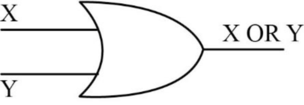
- The truth table for OR operation is as follows,
| X | Y | Z=X OR Y |
| 0 | 0 | 0 |
| 0 | 1 | 1 |
| 1 | 0 | 1 |
| 1 | 1 | 1 |
- In the above table, “X” and “Y” are the inputs, and “Z” is the output.
- In the above table, when “X=0”, and “Y=0”, the output “Z” is “0”, because both the inputs “X” and “Y” contains the value “0”.
- When “X=0”, and “Y=1”, the output “Z” is “1”, because one of the input “Y” contains the value “1”.
- When “X=1”, and “Y=0”, the output “Z” is “1”, because one of the input “X” contains the value “1”.
- When “X=1”, and “Y=1”, the output “Z” is “1”, because both the inputs “X” and “Y” contains the value “1”.
AND function:
- AND function needs two inputs and produces one output.
- It is also known as binary logical function.
- If one or both the inputs are “0”, then one-bit AND operation produces the output “0”.
- If both inputs are “1”, then AND operation produces the output as “1”.
- The following diagram depicts the AND operation,
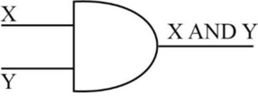
- The truth table for AND operation is as follows,
| X | Y | X AND Y |
| 0 | 0 | 0 |
| 0 | 1 | 0 |
| 1 | 0 | 0 |
| 1 | 1 | 1 |
- In the above table, “X” and “Y” are inputs, and “Z” is output.
- When “X=0”, and “Y=0”, the output is “0”, because both the inputs “X” and “Y” contains the value “0”.
- When “X=0”, and “Y=1”, the output is “0”, because one of the input “X” contains the value “0”.
- When “X=1”, and “Y=0”, the output is “0”, because one of the input “Y” contains the value “0”.
- When “X=1”, and “Y=1”, the output is “1”, because both the inputs “X” and “Y” contains the value “1”.
b.
Explanation of Solution
Function to be implemented for the given criteria:
- Truth table to implement the function “F”, which has the value “1” only when the value of “A” is “1” and the value of “B” is “0” is as follows,
| Inputs | Output | |
| A | B | F |
| 0 | 0 | 0 |
| 0 | 1 | 0 |
| 1 | 0 | 1 |
| 1 | 1 | 0 |
K-Map:
The K-map for the above truth table is as follows,
c.
Explanation of Solution
Function to be implemented for the given criteria:
- The given truth table for the one-bit adder is as follows,
| Inputs | Output | |
| A | B | Sum |
| 0 | 0 | 0 |
| 0 | 1 | 1 |
| 1 | 0 | 1 |
| 1 | 1 | 0 |
K-Map:
The K-map for the above truth table is as follows,
d.
Explanation of Solution
Creation of four-bit adder:
“No”, it is not possible to make a four-bit adder.
Explanation:
- The logic diagram derived in part “c” is a half adder.
- The logic circuit needs four full adder circuits to implement four-bit adder.
- Therefore, using four copies of logic diagram derived in part “c”, it is not possible to make a four-bit adder.
Missing information:
- Carry information is missing in the given truth table...
Expert Solution & Answer
Want to see the full answer?
Check out a sample textbook solution
Chapter 3 Solutions
Introduction To Computing Systems
Ch. 3 - Prob. 1ECh. 3 - Replace the missing parts in the following circuit...Ch. 3 - A two-input AND and a two-input OR are both...Ch. 3 - Replace the missing parts in the following circuit...Ch. 3 - Complete a truth table for the transistor-level...Ch. 3 - For the transistor-level circuit in Figure 3.38,...Ch. 3 - Prob. 7ECh. 3 - The transistor-level circuit below implements the...Ch. 3 - What does the following transistor circuit do?
Ch. 3 - For what values of A, B, C, D, E, and F will the...
Ch. 3 - A student knew that an inverter contained one...Ch. 3 - The following logic diagram produces the logical...Ch. 3 - The following logic circuits consist of two...Ch. 3 - Fill in the truth table for the logical expression...Ch. 3 - Fill in the truth table for a two-input NOR...Ch. 3 - Prob. 19ECh. 3 - How many output lines will a 16-input multiplexer...Ch. 3 - Prob. 21ECh. 3 - Given the following truth table, generate the...Ch. 3 - Prob. 23ECh. 3 - Prob. 24ECh. 3 - Logic circuit 1 in Figure 3.39 has inputs A, B, C....Ch. 3 - You know a byte is eight bits. We call a four-bit...Ch. 3 - Prob. 28ECh. 3 - Prob. 29ECh. 3 - Say the speed of a logic structure depends on the...Ch. 3 - Recall that the adder was built with individual...Ch. 3 - For this question, refer to the figure that...Ch. 3 - Prob. 35ECh. 3 - A comparator circuit has two 1-bit inputs A and B...Ch. 3 - If a computer has eight-byte addressability and...Ch. 3 - Prob. 38ECh. 3 - Refer to Figure 3.21, the diagram of the...Ch. 3 - Given a memory that is addressed by 22 bits and is...Ch. 3 - Prob. 42ECh. 3 - Prob. 43ECh. 3 - Prob. 44ECh. 3 - Prob. 47ECh. 3 - Refer to Figure 3.32. Why are lights 1 and 2...Ch. 3 - Prob. 49ECh. 3 - We have learned that we can write one bit of...Ch. 3 - A student decided to design a latch as shown...
Knowledge Booster


Learn more about
Need a deep-dive on the concept behind this application? Look no further. Learn more about this topic, computer-science and related others by exploring similar questions and additional content below.Recommended textbooks for you
 Database System ConceptsComputer ScienceISBN:9780078022159Author:Abraham Silberschatz Professor, Henry F. Korth, S. SudarshanPublisher:McGraw-Hill Education
 Starting Out with Python (4th Edition)Computer ScienceISBN:9780134444321Author:Tony GaddisPublisher:PEARSON
 Digital Fundamentals (11th Edition)Computer ScienceISBN:9780132737968Author:Thomas L. FloydPublisher:PEARSON
 C How to Program (8th Edition)Computer ScienceISBN:9780133976892Author:Paul J. Deitel, Harvey DeitelPublisher:PEARSON
 Database Systems: Design, Implementation, & Manag...Computer ScienceISBN:9781337627900Author:Carlos Coronel, Steven MorrisPublisher:Cengage Learning
 Programmable Logic ControllersComputer ScienceISBN:9780073373843Author:Frank D. PetruzellaPublisher:McGraw-Hill Education
Database System Concepts
Computer Science
ISBN:9780078022159
Author:Abraham Silberschatz Professor, Henry F. Korth, S. Sudarshan
Publisher:McGraw-Hill Education
Starting Out with Python (4th Edition)
Computer Science
ISBN:9780134444321
Author:Tony Gaddis
Publisher:PEARSON
Digital Fundamentals (11th Edition)
Computer Science
ISBN:9780132737968
Author:Thomas L. Floyd
Publisher:PEARSON
C How to Program (8th Edition)
Computer Science
ISBN:9780133976892
Author:Paul J. Deitel, Harvey Deitel
Publisher:PEARSON
Database Systems: Design, Implementation, & Manag...
Computer Science
ISBN:9781337627900
Author:Carlos Coronel, Steven Morris
Publisher:Cengage Learning
Programmable Logic Controllers
Computer Science
ISBN:9780073373843
Author:Frank D. Petruzella
Publisher:McGraw-Hill Education
Boolean Algebra - Digital Logic and Logic Families - Industrial Electronics; Author: Ekeeda;https://www.youtube.com/watch?v=u7XnJos-_Hs;License: Standard YouTube License, CC-BY
Boolean Algebra 1 – The Laws of Boolean Algebra; Author: Computer Science;https://www.youtube.com/watch?v=EPJf4owqwdA;License: Standard Youtube License