
Concept explainers
Videos
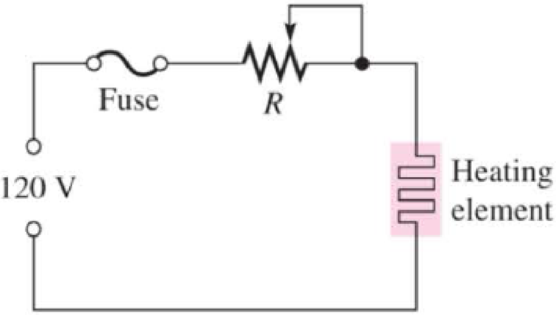
The potentiometer connected as a rheostat in Figure 3–25 is used to control the current to a heating element. When the rheostat is adjusted to a value of 8 Ω or less, the heating element can burn out. What is the rated value of the fuse needed to protect the circuit if the voltage across the heating element at the point of maximum current is 100 V and the voltage across the rheostat is the difference between the heating element voltage and the source voltage?
Figure 3–25

Trending nowThis is a popular solution!

Chapter 3 Solutions
Principles Of Electric Circuits
Additional Engineering Textbook Solutions
Fundamentals of Applied Electromagnetics (7th Edition)
Electric Circuits (10th Edition)
Engineering Electromagnetics
Electrical Engineering: Principles & Applications (7th Edition)
Introductory Circuit Analysis (13th Edition)
Electric Motors and Control Systems


- For the circuit given in Figure 3, determine which light bulb(s) will glow brightly, and which light bulb(s) will glow dimly (assuming all light bulbs are identical).arrow_forwardDetermine what these four voltmeters (A, B, C, D) will register when connected to this circuit in the following positions (assume a battery voltage of 6 volts): Voltmeter A = Voltmeter B = Voltmeter C = Voltmeter D =arrow_forwardThe potentiometer initially has a value of 500 ohms. It is later changed to 750 ohms. Which of the following is true? a. The power consumed by the resistor remains the same regardless of changing the value of the resistance. b. Current passing through the circuit increases with the resistance. c. Voltage across the resistance remains the same because the voltage in the source did not change. d. Current through the voltage source varies with the resistance.arrow_forward
- In the circuiit shown, all six resistors share the same value, R. Calculate the equivalent resistance of R(closed) between points A and B when switch S is closed as a percentage of the equivalent resistance R(open) when switch S is open. If each resistor has a resistance of R = 34.3 Ohms, calculae the resistance of R(closed) between points A and B after switch S is closedarrow_forward3.c. Calculate the value of the shunt resistor, RA, to give a full-scale current reading of 100 mA. Answer in ohms. 3.d. How much resistance is added to a circuit when the 100 mA ammeter in part (c) is inserted to measure current?arrow_forwardFind the voltage drops across the resistors in the circuit of Figure 3.10.25 . Please show all work steps clearlyarrow_forward
- Part 1 After using the UT33B multimeter to check the voltage of the batteries and the resistance of, light bulb and resistors, these are the results: - Voltage of the battery is measured to be 1608 mV, The scale used to measure voltage is 2000mV on the UT33B multimeter - Resistance of the bulb is measured to be 0.24 ohm, The scale used to measure resistance is 200 ohm on the UT33B multimeter - Resistance of the resistor1 (R1) is measured to be 15.2 ohm, The scale used to measure resistance is 200 ohm on the UT33B multimeter - Resistance of the resistor2 (R2) is measured to be 27.2 ohm, The scale used to measure resistance is 200 ohm on the UT33B multimeter Part 2 After connecting a circuit to find the resistance of the light bulb and resistors experimentally using a circuit, these are the results: LIGHT BULB - Resistance of the light bulb and resistors could not be measured on the UT33B multimeter, so the voltage and current were measured and the resistance was found using ohms law.…arrow_forwarddave connects an electric circuit to find the resistance of 100 cm of wire. the battery voltage is 9V. the ammeter is 2A. and the voltmeter is 5V. what is the resistance of the 100cm of wirearrow_forwardThe circuit diagram below is for a robot that walks around the room. It is designed to stop walking when certain conditions are met. a) In which of the following cases will the robot start walking? i. The robot is far from the wall. ii. The battery status is good. iii. The room lights are on. iv. Both i and ii. v. i, ii, and iii. vi. ii and iii, but not i. vii. i and iii, but not ii. b) Explain what happens to the robot if the light is turned off. ______________________________________________________________________________ ______________________________________________________________________________ c) If you remove the light sensor and the AND gate attached to it from the circuit from the circuit, which of the following are true and which are false? i. The robot will continue to walk with a low battery ii. The robot will stop walking if it is close to the wall iii. One of the remaining inputs (proximity sensor and battery status) is irrelevant to whether the robot walks or not.…arrow_forward
- Using the circuit in the image and the figures in the attached table: a. With both switches, SW1 and SW2 left open complete the following: i. Briefly discuss what the three resistors are used for. ii. Determine the total resistance in the circuit. iii. Determine the currents flowing in the circuit. iv. Determine the volt drops around the circuit. v. Use the appropriate Kirchhoff’s law to confirm your results. b. Now close switch SW1 and complete the following: i. Determine the total resistance in the circuit. ii. Determine the currents flowing in the circuit. iii. Determine the volt drops around the circuit. iv. Use the appropriate Kirchhoff’s law to confirm your results. c. Now Whilst keeping SW1 closed close SW2 and complete the following: i. Determine the total resistance in the circuit. ii. Determine the currents flowing in the circuit. iii. Determine the volt drops around the circuit. iv. Use the appropriate Kirchhoff’s law to confirm your results.arrow_forwardWhat is the maximum permissible current in an 82Ω, 2W resistor? What is the maximum voltage that can be applied to the resistor?arrow_forwardA cell of emf ‘E’ and internal resistance ‘r’ was connected in series with an ammeter and a variable resistor. When the resistance of the variable resistor was 10 Ω the current was 80 mA. When the resistance of the variable resistor was changed to 15 Ω the current was 60 mA. 1. Clearly draw a circuit diagram of this arrangement.2. Calculate the emf and the internal resistance of the cell.arrow_forward
 Introductory Circuit Analysis (13th Edition)Electrical EngineeringISBN:9780133923605Author:Robert L. BoylestadPublisher:PEARSON
 Delmar's Standard Textbook Of ElectricityElectrical EngineeringISBN:9781337900348Author:Stephen L. HermanPublisher:Cengage Learning
 Programmable Logic ControllersElectrical EngineeringISBN:9780073373843Author:Frank D. PetruzellaPublisher:McGraw-Hill Education
 Fundamentals of Electric CircuitsElectrical EngineeringISBN:9780078028229Author:Charles K Alexander, Matthew SadikuPublisher:McGraw-Hill Education
 Electric Circuits. (11th Edition)Electrical EngineeringISBN:9780134746968Author:James W. Nilsson, Susan RiedelPublisher:PEARSON
 Engineering ElectromagneticsElectrical EngineeringISBN:9780078028151Author:Hayt, William H. (william Hart), Jr, BUCK, John A.Publisher:Mcgraw-hill Education,