
Principles Of Electric Circuits
10th Edition
ISBN: 9780134879482
Author: Floyd, Thomas L.
Publisher: Pearson,
expand_more
expand_more
format_list_bulleted
Concept explainers
Videos
Textbook Question
Chapter 3, Problem 39P
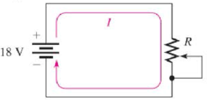
By varying the rheostat (variable resistor) in the circuit of Figure 3-28, you can change the amount of current. (a) The setting of the rheostat is such that the current is 50 mA. What is the resistance value of this setting? (b) To adjust the current to 100 mA, to what resistance value must you set the rheostat? (c) What is the problem with this circuit?
Figure 3-28
Expert Solution & Answer
Want to see the full answer?
Check out a sample textbook solution
Students have asked these similar questions
Based on the diagram, where should I place the terminals of the Ohmeter to measure the resistance across the given terminals, and give the reason/s why it is there./
a.) resistance across 'c' and 'f', and why?b.) resistance across 'b' and 'd' and why?
explain thoroughly. Thank you
A) A carbon resistor has colored bands as shown in Figure 3.
Calculate
The resistance value.
2. The maximum and minimum values of resistance.
A carbon resistor has colored bands as shown in Figure 3.
Figure 3
Calculate
The resistance value.
The maximum and minimum values of resistance.
Chapter 3 Solutions
Principles Of Electric Circuits
Ch. 3 - If the current drops to 10 mA under the same...Ch. 3 - If the sense resistor develops 0.8 V across it,...Ch. 3 - Calculate the current in Figure 3-71 if R is...Ch. 3 - What is the current in mA produced by 1 kV across...Ch. 3 - How much current is there through a 6.8 M resistor...Ch. 3 - In Figure 3-10, how much voltage is required to...Ch. 3 - lf there are 3.2 A through a 47 resistor, what is...Ch. 3 - If there are 450 A through a 3.9 M resistor, what...Ch. 3 - In the circuit of Figure 3-13, how much resistance...Ch. 3 - If one of the grid wires opens, the current drops...
Ch. 3 - If the resistor is changed in Figure 3-14 so that...Ch. 3 - If the total resistance of a circuit increases and...Ch. 3 - Ohms law for finding resistance is R = I/V.Ch. 3 - When milliamps and kilohms are multiplied...Ch. 3 - If a 10 k resistor is connected to a 10 V source,...Ch. 3 - The current in a fixed resistor is directly...Ch. 3 - Ohms law for finding current is I = V/R.Ch. 3 - When microamps and megohms are multiplied, the...Ch. 3 - When voltage is constant, current is inversely...Ch. 3 - Ohms law for finding voltage is V = I/R.Ch. 3 - When I is plotted as a function of V for a fixed...Ch. 3 - Ohms law states that 1. current equals voltage...Ch. 3 - When the voltage across a resistor is doubled, the...Ch. 3 - When 10 V are applied across a 20 resistor, the...Ch. 3 - When there are 10 mA of current through 1.0 k...Ch. 3 - If 20 V are applied across a resistor and there...Ch. 3 - A current of 250 A through a 4.7 k resistor...Ch. 3 - A resistance of 2.2 M is connected across a 1 kV...Ch. 3 - How much resistance is required to limit the...Ch. 3 - An electric heater draws 2.5 A from a 110 V...Ch. 3 - The current through a flashlight bulb is 20 mA and...Ch. 3 - If the current through a fixed resistor goes from...Ch. 3 - If the voltage across a fixed resistor goes from...Ch. 3 - A variable resistor has 5 V across it. If you...Ch. 3 - If the voltage across a resistor increases from 5...Ch. 3 - If larger voltages are applied and results are...Ch. 3 - If the IV curve for a larger value resistor is...Ch. 3 - If the voltmeter reading changes to 175 V, the...Ch. 3 - If is changed to a larger value and the voltmeter...Ch. 3 - If the resistor is removed from the circuit...Ch. 3 - If the resistor is removed from the circuit...Ch. 3 - If the rheostat is adjusted to increase the...Ch. 3 - If the rheostat is adjusted to increase the...Ch. 3 - If the fuse opens, the voltage across the heating...Ch. 3 - If the source voltage increases, the voltage...Ch. 3 - If the fuse is changed to one with a higher...Ch. 3 - If the lamp burns out (opens), the current a....Ch. 3 - If the lamp burns out, the voltage across it a....Ch. 3 - In a circuit consisting of a voltage source and a...Ch. 3 - State the formula used to find I when the values...Ch. 3 - State the formula used to find V when the values...Ch. 3 - State the formula used to find R when the values...Ch. 3 - A variable voltage source is connected to the...Ch. 3 - In a certain circuit, I = 5 mA when V = 1 V....Ch. 3 - Figure 322 is a graph of current versus voltage...Ch. 3 - Plot the currentvoltage relationship for a...Ch. 3 - Plot the currentvoltage relationship for a...Ch. 3 - Determine the current in each circuit in Figure...Ch. 3 - You are measuring the current in a circuit that is...Ch. 3 - (a) If you wish to increase the amount of current...Ch. 3 - Plot a graph of current versus voltage for voltage...Ch. 3 - Does the graph in Problem 13 indicate a linear...Ch. 3 - Figure 3-24 shows an IV curve for a certain light...Ch. 3 - For the bulb graphed in Figure 3-24, what is the...Ch. 3 - Determine the current in each case: a. V = 5 V, R...Ch. 3 - Determine the current in each case: a. V = 9 V, R...Ch. 3 - Assume 200 mV is across a 330 m current sensing...Ch. 3 - A certain resistor has the following color code:...Ch. 3 - A 4-band resistor is connected across the...Ch. 3 - A 5-band resistor is connected across a 12 V...Ch. 3 - If the voltage in Problem 22 is doubled, will a...Ch. 3 - A certain rear window defroster has a resistance...Ch. 3 - If the voltage of the battery in problem 24 drops...Ch. 3 - The potentiometer connected as a rheostat in...Ch. 3 - A 270 current-limiting resistor has a voltage of...Ch. 3 - A small solar cell is connected to a 27 k...Ch. 3 - Calculate the voltage for each value of I and R:...Ch. 3 - Calculate the voltage for each value of I and R:...Ch. 3 - Three amperes of current are measured through a 27...Ch. 3 - Assign a voltage value to each source in the...Ch. 3 - A 6 V source is connected to a 100 resistor by...Ch. 3 - Calculate the resistance of a rheostat for each...Ch. 3 - Calculate the resistance of a rheostat for each...Ch. 3 - Six volts is applied across a resistor. A current...Ch. 3 - The filament of a lamp in the circuit of Figure...Ch. 3 - A certain electrical device has an unknown...Ch. 3 - By varying the rheostat (variable resistor) in the...Ch. 3 - In the light circuit of Figure 329, identify the...Ch. 3 - Assume you have a 32-light string and one of the...
Knowledge Booster


Learn more about
Need a deep-dive on the concept behind this application? Look no further. Learn more about this topic, electrical-engineering and related others by exploring similar questions and additional content below.Similar questions
- A 10,000- resistor has a tolerance of 5%. What are the minimum and maximum values of this resistor?arrow_forwardYou will learn in Chapter 3 that residential lighting loads are based on 3 volt-amperes per ft2 (33 volt-amperes per m2). Determine the minimum lighting load required for an area of 186 m2. Do calculations for both feet squared and meters squared so you can see the difference in answers. To convert meters squared to feet squared, refer to Table 1-8.arrow_forwardThe potentiometer initially has a value of 500 ohms. It is later changed to 750 ohms. Which of the following is true? a. The power consumed by the resistor remains the same regardless of changing the value of the resistance. b. Current passing through the circuit increases with the resistance. c. Voltage across the resistance remains the same because the voltage in the source did not change. d. Current through the voltage source varies with the resistance.arrow_forward
- Determine the current ( i ) for the network shown in figure 3. (The answer is —40amps)arrow_forwardPart 1 After using the UT33B multimeter to check the voltage of the batteries and the resistance of, light bulb and resistors, these are the results: - Voltage of the battery is measured to be 1608 mV, The scale used to measure voltage is 2000mV on the UT33B multimeter - Resistance of the bulb is measured to be 0.24 ohm, The scale used to measure resistance is 200 ohm on the UT33B multimeter - Resistance of the resistor1 (R1) is measured to be 15.2 ohm, The scale used to measure resistance is 200 ohm on the UT33B multimeter - Resistance of the resistor2 (R2) is measured to be 27.2 ohm, The scale used to measure resistance is 200 ohm on the UT33B multimeter Part 2 After connecting a circuit to find the resistance of the light bulb and resistors experimentally using a circuit, these are the results: LIGHT BULB - Resistance of the light bulb and resistors could not be measured on the UT33B multimeter, so the voltage and current were measured and the resistance was found using ohms law.…arrow_forwardFor the circuit given in Figure 3, determine which light bulb(s) will glow brightly, and which light bulb(s) will glow dimly (assuming all light bulbs are identical).arrow_forward
- What is the voltage of the 3Ω resistor?arrow_forward1. Find the current through each resistor 2. Record the voltage across each resistor 3. Explain the result and discussionarrow_forward3.c. Calculate the value of the shunt resistor, RA, to give a full-scale current reading of 100 mA. Answer in ohms. 3.d. How much resistance is added to a circuit when the 100 mA ammeter in part (c) is inserted to measure current?arrow_forward
- 2 - Which of the following is correct for ammeter?I. It is connected in series to the circuit.II. If it is connected in parallel to the circuit, it will short-circuit the branch it is connected to.III. Its internal resistance is very large. A) I, II and III B) Only I C) I and II D) II and III E) I and IIIarrow_forwardcalculate current using ohms law and calculate voltage drop across each resistor (VR1 to VR3)arrow_forwardPart a) Determine the expected voltage reading "Vm" if the multimeter resistance is not considered (i.e. if it is assumed that Rm = ∞) Part b) Suppose that the actual voltage reading on the multimeter is Vm = 6.52 V. Determine the resistance "Rm" of the multimeter.arrow_forward
arrow_back_ios
SEE MORE QUESTIONS
arrow_forward_ios
Recommended textbooks for you
 EBK ELECTRICAL WIRING RESIDENTIALElectrical EngineeringISBN:9781337516549Author:SimmonsPublisher:CENGAGE LEARNING - CONSIGNMENT
 Delmar's Standard Textbook Of ElectricityElectrical EngineeringISBN:9781337900348Author:Stephen L. HermanPublisher:Cengage Learning
EBK ELECTRICAL WIRING RESIDENTIAL
Electrical Engineering
ISBN:9781337516549
Author:Simmons
Publisher:CENGAGE LEARNING - CONSIGNMENT
Delmar's Standard Textbook Of Electricity
Electrical Engineering
ISBN:9781337900348
Author:Stephen L. Herman
Publisher:Cengage Learning
Superposition Theorem; Author: The Organic Chemistry Tutor;https://www.youtube.com/watch?v=EX52BuZxpQM;License: Standard Youtube License