
Videos
Compute the power absorbed by each element of the circuit of Fig. 3.67.
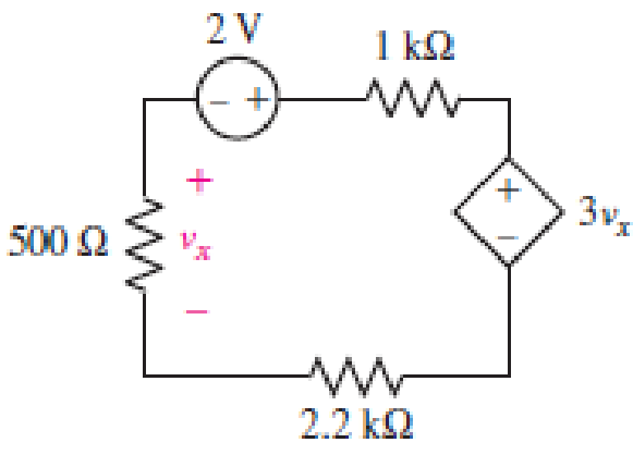
■ FIGURE 3.67
Find power absorbed by each element in the circuit.
Answer to Problem 27E
Power absorbed by independent voltage source is
Explanation of Solution
Formula used:
The expression for power absorbed by voltage source is as follows,
Here,
The expression for power absorbed by resistor is as follows,
Here,
Calculation:
The circuit diagram is redrawn as shown in Figure 1,
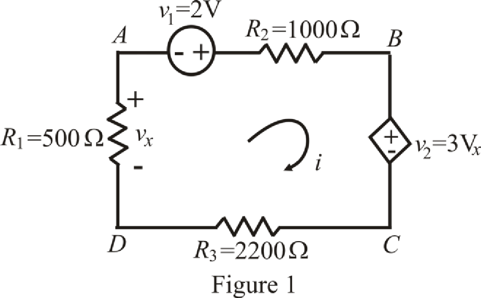
Refer to the redrawn Figure 1,
The expression for KVL in mesh
Here,
The expression for voltage
Here,
The expression for voltage
Here,
Refer to the redrawn Figure 1,
Substitute
Substitute
Rearrange equation (6) and (7),
The equations so formed can be written in matrix form as,
Therefore, by Cramer’s rule,
The determinant of coefficient matrix is as follows,
The 1st determinant is as follows,
The 2nd determinant is as follows,
Simplify for
Simplify for
Substitute
Current is leaving the positive terminal and we are calculating power absorbed means current should leave by negative terminal so we will use magnitude of voltage with negative sign, Thus the value of
Substitute
So power absorbed by independent voltage source
Substitute
So power absorbed by resistor
Substitute
So power absorbed by dependent voltage source
Substitute
So power absorbed by resistor
Substitute
So power absorbed by resistor
Conclusion:
Thus, power absorbed by independent voltage source is
Want to see more full solutions like this?
Chapter 3 Solutions
ENGINEERING CIRCUIT ANALYSIS ACCESS >I<


- Provide complete solution please <3arrow_forward7 Renewable Energy Sources are readily available everywhere, whole year round. Select one: True Falsearrow_forwardA certain appliance requires 225 watts when it is switched on. How much would it cost to run for m minutes, at a cost of d dollars per kilowatt-hour? Express your answer algebraically.arrow_forward
- ________ allows free will but within limits set by Allah a. None of the options b. Islam c. Christianity d. Buddhismarrow_forwardWhich of the three passive components are used to directly sense or measure quantities? Cite at least two quantity examples per component.arrow_forwardA natural waterfalls, 50 meters high, constantly discharges 1.3m3 per second. A minihydroelectric plant is to be constructed at the bottom of the waterfalls. Calculate theelectric generator kW rating, assuming 90% mechanical to electrical conversion efficiencyand water turbine design efficiency of 70%.arrow_forward
- If the dark saturation current of a solar cell is 1.7X10⁻⁸ A/m2, the cell temperature is 27 oC, and the short-circuit current density is 250 A/m2, Vmax = 0.526 V, calculate the open-circuit voltage, Voc; current density at maximum power, Imax.arrow_forwardWhich graph best fits the relationship between x and y? Justify your answer.arrow_forwardDetermine the current labeled I3 in the circuit of Fig.3.55.arrow_forward
- Although drawn so that it may not appear obvious at first glance, the circuitof Fig. 3.73 is in fact a single-node-pair circuit. (a) Determine the powerabsorbed by each resistor. (b) Determine the power supplied by each currentsource. (c) Show that the sum of the absorbed power calculated in (a) is equalto the sum of the supplied power calculated in (c)arrow_forwardKindly answer the following question (as soon as possible). Provide a COMPLETE and CLEAR solution. #3arrow_forwardQ3 / A: The Arton device is designed to configure an ammeter with ranges of 10 ampere, 5 ampere, and 1 ampere, given that the internal resistance of the circuit-breaker circuit is 50 ohms and the full current deviation is 1 milliampere.arrow_forward
 Introductory Circuit Analysis (13th Edition)Electrical EngineeringISBN:9780133923605Author:Robert L. BoylestadPublisher:PEARSON
 Delmar's Standard Textbook Of ElectricityElectrical EngineeringISBN:9781337900348Author:Stephen L. HermanPublisher:Cengage Learning
 Programmable Logic ControllersElectrical EngineeringISBN:9780073373843Author:Frank D. PetruzellaPublisher:McGraw-Hill Education
 Fundamentals of Electric CircuitsElectrical EngineeringISBN:9780078028229Author:Charles K Alexander, Matthew SadikuPublisher:McGraw-Hill Education
 Electric Circuits. (11th Edition)Electrical EngineeringISBN:9780134746968Author:James W. Nilsson, Susan RiedelPublisher:PEARSON
 Engineering ElectromagneticsElectrical EngineeringISBN:9780078028151Author:Hayt, William H. (william Hart), Jr, BUCK, John A.Publisher:Mcgraw-hill Education,