
Concept explainers
(a)
Find current through
(a)
Answer to Problem 59E
The current through
Explanation of Solution
Given data:
Value of trans-conductance
Value of voltage supply
Calculation:
The redrawn circuit is shown in Figure 1.
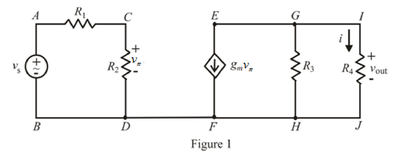
Refer to the Figure 1.
The expression for voltage division across resistance
Here,
The expression for current division rule across resistance
Here,
Substitute
Solve for
Substitute
Solve for
Conclusion:
Thus, the current across the
(b)
Find the amplifier output voltage
(b)
Answer to Problem 59E
The amplifier output voltage
Explanation of Solution
Calculation:
Refer to the Figure 1.
The expression for ohm’s law across resistance
Here,
Refer to the Figure 1.
Substitute
Conclusion:
Thus, the amplifier output voltage in the circuit is
(c)
Check whether the circuit can amplify the signal.
(c)
Answer to Problem 59E
The amplified output voltage can’t amplify the input signal because
Explanation of Solution
Refer to Figure 1
The amplified output voltage
For the amplification, the desired condition must satisfy which is
Conclusion:
Thus, the amplified output voltage can’t amplify the input signal because
(d)
Check whether the circuit can amplify the signal for input voltage
(d)
Answer to Problem 59E
The circuit can amplify the input signal because it satisfies the condition
Explanation of Solution
Refer to Figure 1
The amplified output voltage
For the amplification, the desired condition must satisfy which is
Conclusion:
Thus, circuit can amplify the input signal because it satisfies the condition
Want to see more full solutions like this?
Chapter 3 Solutions
ENGINEERING CIRCUIT ANALYSIS ACCESS >I<


- Integrately design a 5-stage Voltmeter and 3-stage Ammeter using a galvanometer.arrow_forwardQ3:- Design the circuit shown in Fig.(3) , to give a voltage gain = 20 Assume Veso =3V , Vbso =4V, Ing =5 mA and K=2 mA / V? Rin =1 MQ Vop =24Varrow_forwardCompanies designs, creates, and sells Integrated Circuits (chips). What do your buyers useto compare your IC products against your competition’s? Give 3 types of IC benchmarkmeasurements in short answerarrow_forward
- For the network in Fig. 3.6, establish a measurement model considering:(a) PI2 and P I 3 as state variables; (b) PI and P3 as state variables. Comparethe results with those obtained for Example 3.6. Discuss the pros and consof each of the three choices of state variables. Detailed answer is needed.arrow_forwardIn the circuit of Fig.3.60, it is determined that v1= 3V and v3 = 1.5 V. Calculate vR and V2arrow_forwardDesign 7-step Voltmeter and 3-step Ammeter using galvanometer as integrated.arrow_forward
- engineering economics Valley Rendering, Inc. is considering purchasing a new flotation system for grease recovery. The company can finance a $150,000 system at 5% per year compound interest or 5.5% per year simple interest. If the total amount owed is due in a single payment at the end of 3 years, (a) which interest rate should the company select, and (b) how much is the difference in interest between the two schemes?arrow_forwardObtain the node voltages in the circuit of Fig. 3.4. Answer: v1=2 V, v2=14 V.arrow_forwardGiven: R= 482 ohms, L= 0.8H, C= 30 microFarradInstruction: Solve for Vc, IL, VR. Provide detailed solution for it. See the attached picture for the circuit diagram.arrow_forward
 Introductory Circuit Analysis (13th Edition)Electrical EngineeringISBN:9780133923605Author:Robert L. BoylestadPublisher:PEARSON
 Delmar's Standard Textbook Of ElectricityElectrical EngineeringISBN:9781337900348Author:Stephen L. HermanPublisher:Cengage Learning
 Programmable Logic ControllersElectrical EngineeringISBN:9780073373843Author:Frank D. PetruzellaPublisher:McGraw-Hill Education
 Fundamentals of Electric CircuitsElectrical EngineeringISBN:9780078028229Author:Charles K Alexander, Matthew SadikuPublisher:McGraw-Hill Education
 Electric Circuits. (11th Edition)Electrical EngineeringISBN:9780134746968Author:James W. Nilsson, Susan RiedelPublisher:PEARSON
 Engineering ElectromagneticsElectrical EngineeringISBN:9780078028151Author:Hayt, William H. (william Hart), Jr, BUCK, John A.Publisher:Mcgraw-hill Education,