
Concept explainers
Videos
Compute the power absorbed by each element in the circuit of Fig. 3.68 if the mysterious element X is (a) a 13 Ω resistor; (b) a dependent voltage source labeled 4v1, “+” reference on top; (c) a dependent voltage source labeled 4ix, “+” reference on top.
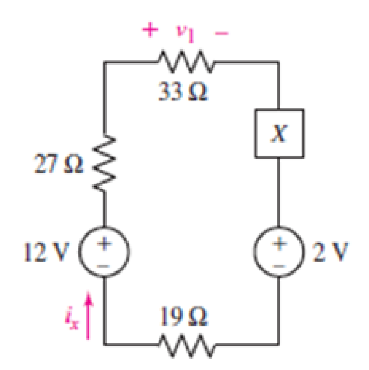
FIGURE 3.68
(a)
Find the power absorbed by each element.
Answer to Problem 28E
Power absorbed by
Explanation of Solution
Given Data:
Element
Formula used:
The expression for power absorbed by voltage source is as follows.
Here,
The expression for power absorbed by resistor is as follows.
Here,
Calculation:
The circuit diagram is redrawn as shown in Figure 1.
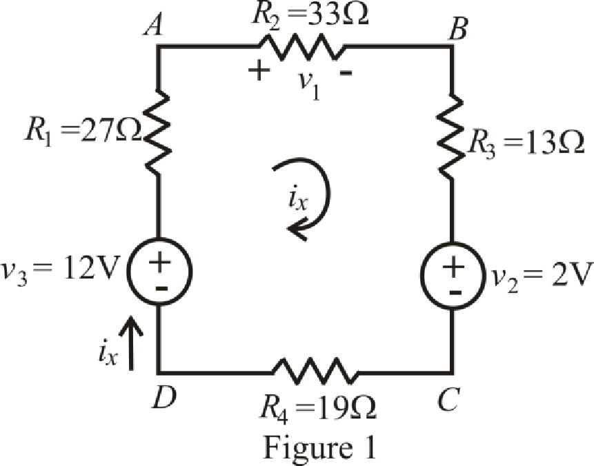
Refer to the redrawn Figure 1.
The expression for KVL in mesh
Here,
Substitute
Rearrange equation (4) for
Current is leaving the positive terminal and we are calculating power absorbed hence current should leave by negative terminal so we will use magnitude of voltage with negative sign, therefore, value of
Substitute
So power absorbed by independent voltage source
Substitute
So, the power absorbed by resistor
Substitute
So power absorbed by resistor
Substitute
So power absorbed by resistor
Substitute
So power absorbed by independent voltage source
Substitute
So power absorbed by resistor
Conclusion:
Thus, power absorbed by
(b)
Find power absorbed by each element.
Answer to Problem 28E
Power absorbed by
Explanation of Solution
Given Data:
Element
Calculation:
The circuit diagram is redrawn as shown in Figure 2,
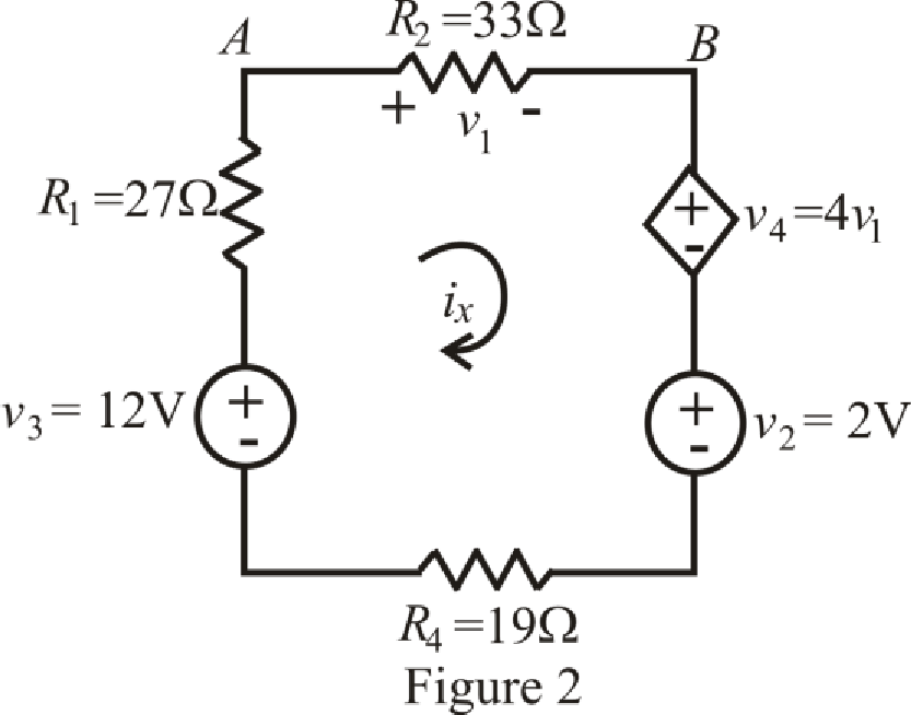
Refer to the redrawn Figure 2,
The expression for KVL in mesh
Here,
The expression for voltage
Here,
The expression for voltage
Here,
Refer to the redrawn Figure 2,
Substitute
Substitute
Rearrange equation (9) for
Current is leaving the positive terminal and we are calculating power absorbed hence current should leave by negative terminal so we will use magnitude of voltage with negative sign, therefore, value of
Substitute
So power absorbed by independent voltage source
Substitute
So power absorbed by resistor
Substitute
So power absorbed by resistor
Substitute
Substitute
Substitute
So power absorbed by dependent voltage source
Substitute
So power absorbed by independent voltage source
Substitute
So power absorbed by resistor
Conclusion:
Thus, power absorbed by
(c)
Find power absorbed by each element.
Answer to Problem 28E
Power absorbed by
Explanation of Solution
Given Data:
Element
Calculation:
The circuit diagram is redrawn as shown in Figure 3.
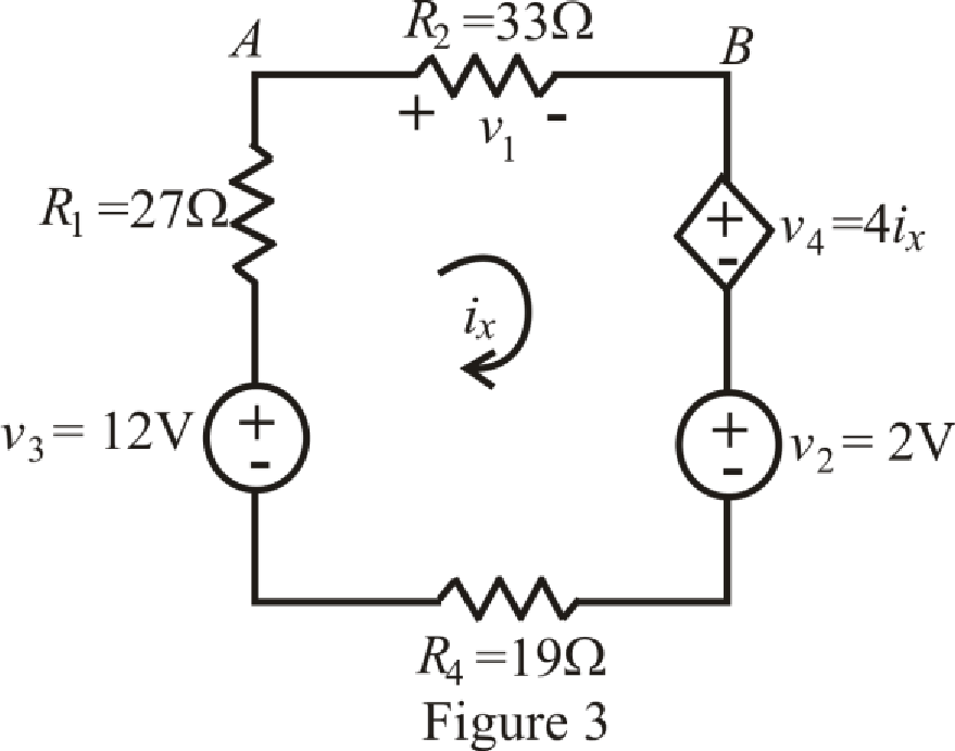
Refer to the redrawn Figure 3,
The expression for KVL in mesh
Here,
The expression for voltage
Here,
Refer to the redrawn Figure 2,
Substitute
Rearrange equation (12) for
Current is leaving the positive terminal and we are calculating power absorbed hence current should leave by negative terminal so we will use magnitude of voltage with negative sign, therefore, value of
Substitute
So power absorbed by independent voltage source
Substitute
So power absorbed by resistor
Substitute
So power absorbed by resistor
Substitute
Substitute
So power absorbed by dependent voltage source
Substitute
So power absorbed by independent voltage source
Substitute
So power absorbed by resistor
Conclusion:
Thus, power absorbed by
Want to see more full solutions like this?
Chapter 3 Solutions
ENGINEERING CIRCUIT...(LL)>CUSTOM PKG.<


- Q3// i) Find the total energy stored in the circuit of Figure 3. 2H 3 H 12 V 6 A 2F Figure 3arrow_forwardi need the answer quicklyarrow_forward1. A galvanometer is to be used as a multi-range dc voltmeter. If the full scale current deflection is 100μA and the galvanometer internal resistance is 2k2, calculate the ohmic value or R1, R2 and R3 for the meter to be extended as 10V, 100V and 750V voltmeter. 750V R3 100V R2 ww R1 10V IFSD = 100μA Rm = 2000 ohmsarrow_forward
- 1. Determine the following: (a) .o be Total Current and Total LEC Power of the circuit; (b) the VA = 120 V current passing through each resistors; (c) The voltage drop across each resistors; (d) the power taken by each resistor. R = 30 2 . MERVAN P, DE MOHAMMEI I = ? R3 = 50 2 So oti 13 =? st given to the earer, for this work to be presented or R, = 40 2 LECTURE SLIDE O MEVIN ,OHAJAME SLIDE ON I PEMOHAMM R4 = 60 2 14 = ? ork to be presented or shown to others. + Rs = 60 2 shown to ohers. er, for this work to be pre Cthers. rthis work to be presented or shown R = 70 2 I6 = ? co the hown to others. 1, = ? TURE SLIDES MOHAMN R, = 80 2 CONSENT wasot given to the bearer, for this work to farrow_forwardQ3: Calculate the voltage of 252 resistance in the following circuit. 300 100 (30v 300 250 www MAM www-arrow_forwardthank you :) need help understanding it wellarrow_forward
- Needs Complete solution with 100 % accuracy.arrow_forwarda) Briefly explain the power rating of a resistor b) Carbon composition resistors are available with power rating of /8 W, ¼ W, ½ W, and 2 W. Given the circuit values of voltage, current, and/or resistance in each of the following. Determine the minimum power rating that the carbon composition resistor can have. 1 i. R = 10 2 V = 4 V |= 20 mA ii. R = 1.5 k. ii. V = 50 mV | = 0.2 A 2.arrow_forward3.15. Plot the V out as a function of Vx in the cir- cuit of Fig. 3.72. Assume Vx = Vo sin wt and a constant-voltage diode model. + Vx R Vout VB Figure 3.72arrow_forward
- A. Explain the relation between current and voltage in the basic component of electrical circuit. B. Find the equivalent resistance of the circuit given in figure 3 between A and B, between E and F E Fig 3 A www fur 252 452 1Q B 89 www D 202 www Farrow_forwardQ.1 a) What function does R1 serve with respect to setting the Maximum Voltage output? Refer to voltage dividers in your answer b) What function does R3 serve with respect to setting the Minimum Voltage output? Refer to voltage dividers in your answer.arrow_forwardDraw the below given circuit. Change value of components according to your circuit. Use ammeter, voltmeter and ohmmeter to measure the current, voltage and resistence. Use Norton's theorem to find the current flowing through R 2 resistor shown in figure. R1=35 N, R2=50 N, R3=30 N, R4=20 Q, R=10 N and V=70 volts.arrow_forward
 Introductory Circuit Analysis (13th Edition)Electrical EngineeringISBN:9780133923605Author:Robert L. BoylestadPublisher:PEARSON
 Delmar's Standard Textbook Of ElectricityElectrical EngineeringISBN:9781337900348Author:Stephen L. HermanPublisher:Cengage Learning
 Programmable Logic ControllersElectrical EngineeringISBN:9780073373843Author:Frank D. PetruzellaPublisher:McGraw-Hill Education
 Fundamentals of Electric CircuitsElectrical EngineeringISBN:9780078028229Author:Charles K Alexander, Matthew SadikuPublisher:McGraw-Hill Education
 Electric Circuits. (11th Edition)Electrical EngineeringISBN:9780134746968Author:James W. Nilsson, Susan RiedelPublisher:PEARSON
 Engineering ElectromagneticsElectrical EngineeringISBN:9780078028151Author:Hayt, William H. (william Hart), Jr, BUCK, John A.Publisher:Mcgraw-hill Education,