
Videos
Consider the seven-element circuit depicted in Fig. 3.99. (a) How many nodes, loops, and branches does it contain? (b) Calculate the current flowing through each resistor. (c) Determine the voltage across the current source, assuming the top terminal is the positive reference terminal.
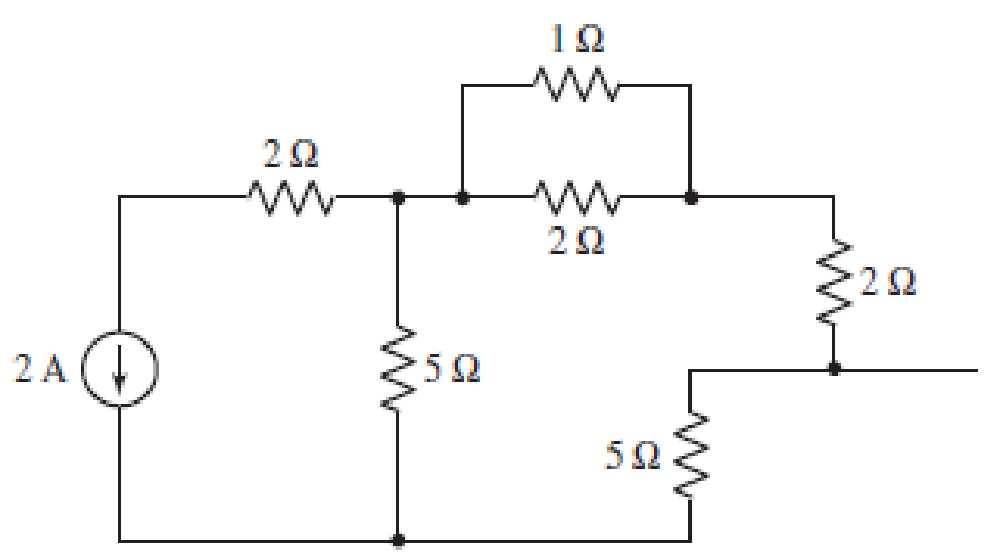
■ FIGURE 3.99
(a)
Find the number of nodes, number of loops and number of branches in the circuit.
Answer to Problem 63E
Number of nodes in the circuit is
Explanation of Solution
The circuit diagram is redrawn as shown in Figure 1.
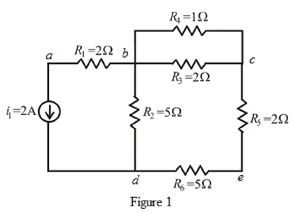
Refer to the redrawn Figure 1.
A point where two or more branches have common connection is known as node.
In Figure 1 two branches are connected at point
Each electrical element or device present in the circuit is known as branch.
There is
The circuit diagram is redrawn as shown in Figure 2,
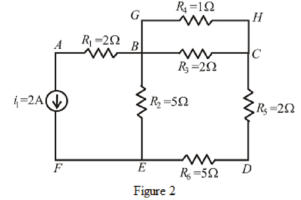
Refer to the redrawn Figure 2,
If starting and ending node is same for a path then it is known as closed path or loop.
Conclusion:
Thus, the number of nodes in the circuit is
(b)
Find the value of current through each resistor.
Answer to Problem 63E
The value of current through
Explanation of Solution
Formula used:
The expression for parallel combination of resistance is as follows.
Here,
Calculation:
The circuit diagram is redrawn as shown in Figure 3.
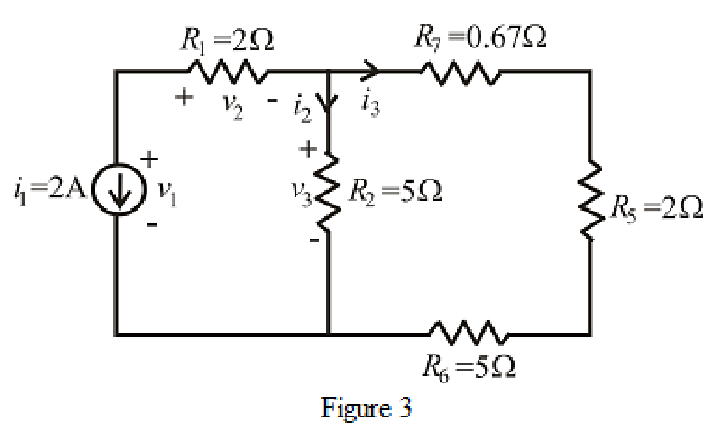
Refer to the redrawn Figure 3.
The expression for current
Here,
The expression for current
Here,
Refer to the redrawn Figure 1.
The expression for current
Here,
The expression for current
Here,
Refer to the redrawn Figure 1.
As
Rearrange for
Refer to the redrawn Figure 3.
As current source direction is downward means change sign of current means value of current is
Substitute
As resistor
So value of current through resistor
Substitute
So, the value of current through resistor
Refer to the redrawn Figure 1.
Substitute
So, the value of current through resistor
Substitute
So, the value of current through resistor
As resistor
Conclusion:
Thus, the value of current through
(c)
Find value of voltage across current source.
Answer to Problem 63E
The voltage across current source is
Explanation of Solution
Formula used:
The expression for voltage is as follows.
Here,
Calculation:
Refer to the redrawn Figure 3.
The expression for voltage
Here,
Refer to the redrawn Figure 3.
Substitute
So value of voltage
Substitute
So value of voltage
Substitute
Conclusion:
Thus, the voltage across current source is
Want to see more full solutions like this?
Chapter 3 Solutions
ENGINEERING CIRCUIT...(LL)>CUSTOM PKG.<


- 3arrow_forwardDirections: The illustration below shows the components of a simple circuit diagram. Choose from the choices on the left the best term or description that will match each component and its function. Write your answer on the prescribed box. • Battery Component: Function: Load Switch • Wire Converts electrical Component: Component: energy into heat, light, or mechanical Function: Function: energy • Completes or breaks circuit by allowing or stopping current from flowing • Provides a route for Component Function: the current to flow through • Supplies electrical energy that causes current flowarrow_forwardWrite legible and show your complete solutionarrow_forward
- Find the voltages at nodes a, b, c, and d in the circuit below and show the system of equations fully. You may solve the system of equations using whatever tool(s) you are comfortable with.arrow_forwardRequired information The figure shows a simplified circuit diagram for an automobile. The equivalent resistor R represents the total electrical load due to spark plugs, lights, radio, fans, starter, rear window defroster, and the like in parallel. Alternator Battery 14.0 V R₁ 12.0 V R₂ R where R₁ = 94.0 m2 and R₂ = 41.0 m2. What is the terminal voltage of the battery?arrow_forwardQ3) A) A moving-coil instrument gives a f.s.d. when the current is 200 µA and its resistance is 200 2. Calculate the value of shunt resistance to be connected in parallel with the meter to enable it to be used as an ammeter for measuring currents up to 500 mA.arrow_forward
- Needs Complete solution.arrow_forwardLMH_chapter3-part 1-homework [Protected View] PowerPoint ĐĂNG PHẠM HỒNG 困 O X File Home Insert Design Transitions Animations Slide Show Review View Help Tell me what you want to do & Share PROTECTED VIEW Be careful-files from the Internet can contain viruses. Unless you need to edit, it's safer to stay in Protected View. Enable Editing 1 HW14 Chapter III AC Circuit Analysis Homework part 1 Reading: Chapter 05 Textbook: Fundamental of Electric 5.7 The op amp in Fig. 5.46 has R; = 100 kN, R, = 100 0, A = 100,000. Find the differential voltage va and the output voltage v,. Circuits Textbook HW14 5.7 The op amp in Fig 5.46 has R, - 100 k, R, - 100 2, 4 - 100,000. Find he dillerential voltage e, and the output voltage e. 10 100 k I mv E) HW15 10 k2 100 k2 5.10 Find the gain /v, of the circait in Fig. 5.49. ww 37 ko 20 k2 1 mV 10 ka 4 HW16 5.13 Find u, andi, in the circuit of Fig. 5.52. E90 ka 100 ka ww 10 ka 50 k2 Slide 2 of 14 English (United States) Comments 90% 11:49 AM O Type here to…arrow_forward7. If a third resistor (R3), identical to the other two, is added in parallel with the first two, then the electric potential difference (voltage drop) across each of the three individual resistors will a. increase. b. decrease c. remain the same 8. Which of the following statements is true about resistance? (State True or False AND EXPLAIN YOUR REASON AND SHOW CALCULATIONS).arrow_forward
- Can you please solve this question in electrical circuitsarrow_forwardA sensitive ammeter (micro-ammeter) is used to manufacture an analog DC voltmeter. The ammeter has the characteristics: 100µA full-scale indication, internal resistance Ri=200ohm. Voltmeter Rs V R = Ri HA Measured_Voltage Calculate the series resistor Rs to obtain a voltmeter able to measure 50V (full scale). 5.9kohm 6kohm 119.9kohm 120kohm 199.5kohm 200kohm 499.8kohm 500kohm (hparrow_forwardQuestion answerarrow_forward
 Introductory Circuit Analysis (13th Edition)Electrical EngineeringISBN:9780133923605Author:Robert L. BoylestadPublisher:PEARSON
 Delmar's Standard Textbook Of ElectricityElectrical EngineeringISBN:9781337900348Author:Stephen L. HermanPublisher:Cengage Learning
 Programmable Logic ControllersElectrical EngineeringISBN:9780073373843Author:Frank D. PetruzellaPublisher:McGraw-Hill Education
 Fundamentals of Electric CircuitsElectrical EngineeringISBN:9780078028229Author:Charles K Alexander, Matthew SadikuPublisher:McGraw-Hill Education
 Electric Circuits. (11th Edition)Electrical EngineeringISBN:9780134746968Author:James W. Nilsson, Susan RiedelPublisher:PEARSON
 Engineering ElectromagneticsElectrical EngineeringISBN:9780078028151Author:Hayt, William H. (william Hart), Jr, BUCK, John A.Publisher:Mcgraw-hill Education,