
Concept explainers
Videos
Determine the cause for each set of symptoms. Refer to Figure 3-27.
Figure 3-27
The meter indicate the correct readings for this circuit.
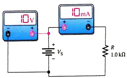
1. Sympotm: The ammeter reading is zero, and the voltmeter reading is 0 V.
Cause:
Want to see the full answer?
Check out a sample textbook solution
Chapter 3 Solutions
Electric Circuits Fundamentals & Lab Mnl Pk


- 2 - Which of the following is correct for ammeter?I. It is connected in series to the circuit.II. If it is connected in parallel to the circuit, it will short-circuit the branch it is connected to.III. Its internal resistance is very large. A) I, II and III B) Only I C) I and II D) II and III E) I and IIIarrow_forwardA circuit has 3 light bulbs in series. The resistance of each light bulb is 10 ohms. 1. a. How do the voltages across each individual light bulb compare to each other? b. How do the voltages across each individual bulb compare to the voltage of the battery?arrow_forwardYou will learn in Chapter 3 that residential lighting loads are based on 3 volt-amperes per ft2 (33 volt-amperes per m2). Determine the minimum lighting load required for an area of 186 m2. Do calculations for both feet squared and meters squared so you can see the difference in answers. To convert meters squared to feet squared, refer to Table 1-8.arrow_forward
- True or False: Ohms law applies to all types of electrical circuits.arrow_forwardWhat is the maximum permissible current in an 82Ω, 2W resistor? What is the maximum voltage that can be applied to the resistor?arrow_forward1.a voltmeter cannot be used to check for proper circuit grounding.Ture or falsearrow_forward
- Special ProcedureIn figure 2.4 (same circuit as figure 2.1), using the Resistance Mode of the Multimeter,a. what is the measured resistance across terminals ‘c’ and ‘f’? Explain.b. what is the measured resistance across terminals ‘b’ and ‘d’? Explain.arrow_forwardThree resistors R1,R2, and R3, are connected in series and to a 120-volt source. If R2 = 2R1, R3 = 3R1, and the total power taken by the circuit is 200 watts, calculate (a) the resistance of each resistor, ( b) the power in each resistorarrow_forwardPart 1 After using the UT33B multimeter to check the voltage of the batteries and the resistance of, light bulb and resistors, these are the results: - Voltage of the battery is measured to be 1608 mV, The scale used to measure voltage is 2000mV on the UT33B multimeter - Resistance of the bulb is measured to be 0.24 ohm, The scale used to measure resistance is 200 ohm on the UT33B multimeter - Resistance of the resistor1 (R1) is measured to be 15.2 ohm, The scale used to measure resistance is 200 ohm on the UT33B multimeter - Resistance of the resistor2 (R2) is measured to be 27.2 ohm, The scale used to measure resistance is 200 ohm on the UT33B multimeter Part 2 After connecting a circuit to find the resistance of the light bulb and resistors experimentally using a circuit, these are the results: LIGHT BULB - Resistance of the light bulb and resistors could not be measured on the UT33B multimeter, so the voltage and current were measured and the resistance was found using ohms law.…arrow_forward
- Give the value of the following resistors: (GIVE SOLUTIONS)(Must write final value to short notation using KOhms, MOhms, etc. if applicable)1. Red, red ,orange, silver2. Blue, red, orange, gold3. Brown, Black, Orange, gold4. Red, Green, blue, gold5. Violet, green, red, silverarrow_forwardFind the ammeter and voltmeter reading . Please answer all subpart either dislike Please all subpartarrow_forwardBased on the diagram, where should I place the terminals of the Ohmeter to measure the resistance across the given terminals, and give the reason/s why it is there./ a.) resistance across 'c' and 'f', and why?b.) resistance across 'b' and 'd' and why? explain thoroughly. Thank youarrow_forward
 EBK ELECTRICAL WIRING RESIDENTIALElectrical EngineeringISBN:9781337516549Author:SimmonsPublisher:CENGAGE LEARNING - CONSIGNMENT
 Electricity for Refrigeration, Heating, and Air C...Mechanical EngineeringISBN:9781337399128Author:Russell E. SmithPublisher:Cengage Learning